TMDS361B
SLLS988A –SEPTEMBER 2009–REVISED JULY 2011
www.ti.com
AVCC(4)
(5)
R
R
T
T
<2-inch(6) 50-W
Transmission Line
SMA
SMA
SMA
Coax
Coax
Coax
Coax
Data+
Data–
RX
+EQ
OUT
<2-inch(6) 50-W
Transmission Line
SMA
Parallel
BERT
Jitter Testnnn
Instrument(2, 3)
HDMI Cable(1)
AVCC
TMDS361B
OUT
1000-mVpp
Differential
R
T
R
T
<2-inch(6) 50-W
Transmission Line
SMA
SMA
SMA
SMA
Coax
Coax
Coax
Coax
Clk+
Clk–
RX
+EQ
<2-inch(6) 50-W
Transmission Line
Jitter Testnnn
Instrument(2, 3)
TTP4
TTP1
TTP2
TTP3
B0331-11
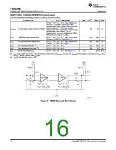
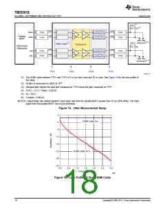
(1) The HDMI cable between TTP1 and TTP2 is 0 m (no loss) case and 20 m case. See Figure 15 for the loss profile of
the cable.
(2) All jitter is measured at a BER of 10–9
.
(3) Residual jitter reflects the total jitter measured at TTP4 minus the jitter measured at TTP1.
(4) AVCC = 3.3 V; VSadj = 4.02 kΩ.
(5) RT = 50 Ω.
(6) 2 inches = 5,08 cm.
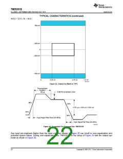
NOTES: Output edge rate default (fastest): input edge rate from the parallel BERT greater than 75 ps (20%–80%). The input
signal from the parallel BERT has no pre-emphasis.
Figure 14. Jitter Measurement Setup
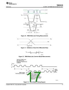
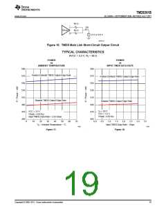
2
HDMI Cable 0 m
−3
−8
−13
−18
−23
−28
−33
HDMI Cable 20 m
0.0
0.5
1.0
1.5
2.0
2.5
3.0
f − Frequency − GHz
G001
Figure 15. Loss Profile of 20-m HDMI Cable
18
Copyright © 2009–2011, Texas Instruments Incorporated

 TI [ TEXAS INSTRUMENTS ]