TMDS361B
www.ti.com
SLLS988A –SEPTEMBER 2009–REVISED JULY 2011
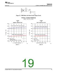
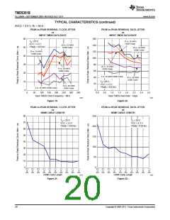
TYPICAL CHARACTERISTICS (continued)
AVCC = 3.3 V, RT = 50 Ω
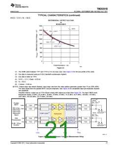
DIFFERENTIAL OUTPUT VOLTAGE
vs
RESISTANCE
1600
1400
1200
1000
800
600
400
200
0
T
A
= 25°C
VCC = 3.6 V
VCC = 3.3 V
VCC = 3 V
3
4
5
6
7
VSadj Resistance − kΩ
G008
Figure 23.
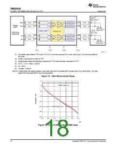
(1) The HDMI cable between TTP1 and TTP2 is 0 m (no loss) case. See Figure 15 for the loss profile of the cable.
(2) Eye data is measured using an 8-GHz bandwith oscilloscope (Agilent).
(3) Eye data is taken at TTP4.
(4) AVCC = 3.3 V; VSadj = 4.02 kΩ.
(5) RT = 50 Ω.
(6) 2 inches = 5,08 cm.
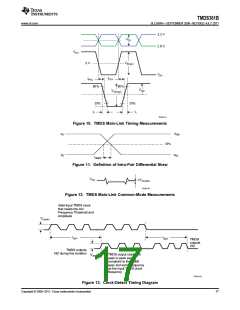
NOTES: Output edge rate default (fastest): input edge rate from the video pattern generator greater than 75 ps (20%–80%).
The input signal from the parallel BERT has pre-emphasis. See Figure 26 for acceptable input pre-emphasis duration
and amplitude.
Pass/fail criterion: output eye at TTP4 should comply with output eye mask (See Figure 25). The input TMDS clock
frequencies tested: 25 MHz, 30.24 MHz, 36 MHz, 54 MHz, 65 MHz, 74.25 MHz, 84.75 MHz, 108 MHz, 135 MHz,
148.5 MHz, 185.625 MHz, 222.75 MHz, 297 MHz.
AVCC(4)
(5)
R
R
T
T
Parallel
BERT
<2-inch(6) 50-W
Transmission Line
SMA
SMA
SMA
SMA
Coax
Coax
Coax
Coax
Data+
Data–
RX
+EQ
OUT
<2-inch(6) 50-W
Transmission Line
800-mVpp,
1000-mVpp,
1200-mVpp,
Differential
Signal
Eye Testnnn
Instrument(2, 3)
HDMI Cable(1)
AVCC
TMDS361B
OUT
R
T
R
T
<2-inch(6) 50-W
Transmission Line
SMA
SMA
SMA
SMA
Coax
Coax
Coax
Coax
With
Preemphasis
Clk+
Clk–
RX
+EQ
<2-inch(6) 50-W
Transmission Line
(3-dB, 120-ps
Duration
Eye Testnnn
Instrument(2, 3)
TTP4
TTP1
TTP2
TTP3
B0331-12
Figure 24. Input Pre-Emphasis Tolerance-Measurement Setup
Copyright © 2009–2011, Texas Instruments Incorporated
21

 TI [ TEXAS INSTRUMENTS ]