TLK10002
SLLSE75 –MAY 2011
www.ti.com
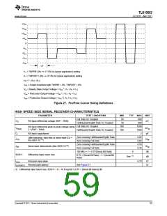
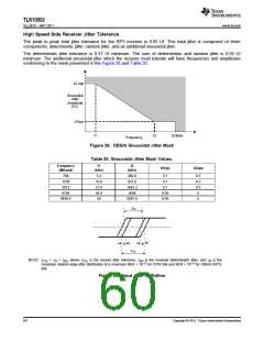
High Speed Side Receiver Jitter Tolerance
The peak to peak total jitter tolerance for the RP3 receiver is 0.65 UI. This total jitter is composed of three
components; deterministic jitter, random jitter, and an additional sinusoidal jitter.
The deterministic jitter tolerance is 0.37 UI minimum. The sum of deterministic and random jitter is 0.55 UI
minimum. The additional sinusoidal jitter which the receiver must tolerate will have frequencies and amplitudes
conforming to the mask presented in the Figure 28 and Table 20.
UI 2pp
Sinusoidal
Jitter
Amplitude
(UI)
UI1pp
f1
f2
20 MHz
Frequency
Figure 28. OBSAI Sinusoidal Jitter Mask
Table 20. Sinusoidal Jitter Mask Values.
Frequency
(MBaud)
f1
(kHz)
f2
(kHz)
UI1pp
UI2pp
768
1536
3072
6144
9830.4
5.4
10.9
21.8
36.9
59
460.8
921.6
1843.2
3686
0.1
0.1
8.5
8.5
8.5
5
0.1
0.05
0.05
5897.6
5
JDR
JR
JR
JTOL
NOTE: JTOL = JR + JDR, where JTOL is the receive jitter tolerance, JDR is the received deterministic jitter, and JR is the
Gaussian random edge jitter distribution at a maximum BER = 10-12 for CPRI link and BER = 10-15 for OBSAI (RP3)
link.
Figure 29. Input Jitter Definition
60
Copyright © 2011, Texas Instruments Incorporated

 TI [ TEXAS INSTRUMENTS ]