TLC7528C, TLC7528E, TLC7528I
DUAL 8-BIT MULTIPLYING
DIGITAL-TO-ANALOG CONVERTERS
SLAS062B – JANUARY 1987 – REVISED MARCH 2000
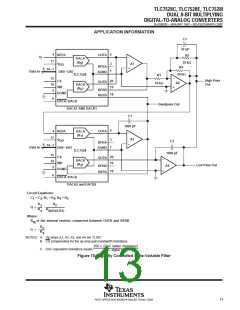
APPLICATION INFORMATION
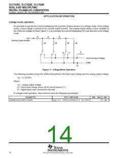
voltage-mode operation
It is possible to operate the current multiplying D/A converter of these devices in a voltage mode. In the voltage
mode, a fixed voltage is placed on the current output terminal. The analog output voltage is then available at
the reference voltage terminal. Figure 11 is an example of a current multiplying D/A, that operates in the voltage
mode.
R
R
R
REF
(Analog Output Voltage)
2R
2R
2R
2R
R
“0”
“1”
Out (Fixed Input Voltage)
AGND
Figure 11. Voltage-Mode Operation
The following equation shows the relationship between the fixed input voltage and the analog output voltage:
V
= V (D/256)
I
O
Where:
V
= analog output voltage
O
V = fixed input voltage (must not be forced below 0 V.)
I
D = digital input code converted to decimal
In voltage-mode operation, these devices meet the following specification:
PARAMETER
Linearity error at REFA or REFB
TEST CONDITIONS
MIN
MAX
UNIT
V
DD
= 5 V, OUTA or OUTB at 2.5 V,
T
A
= 25°C
1
LSB
14
POST OFFICE BOX 655303 • DALLAS, TEXAS 75265

 TI [ TEXAS INSTRUMENTS ]