TAS5711
SLOS600 –DECEMBER 2009
www.ti.com
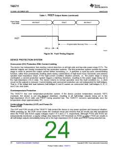
Table 1. FAULT Output States (continued)
Power Stage
Fault State
NO-FAULT
FAULT
NO-FAULT
FAULT
Programmable Recovery Time
~300 ns
T0450-01
Figure 36. Fault Timing Diagram
DEVICE PROTECTION SYSTEM
Overcurrent (OC) Protection With Current Limiting
The device has independent, fast-reacting current detectors on all high-side and low-side power-stage FETs. The
detector outputs are closely monitored by two protection systems. The first protection system controls the power
stage in order to prevent the output current further increasing, i.e., it performs a cycle-by-cycle current-limiting
function, rather than prematurely shutting down during combinations of high-level music transients and extreme
speaker load impedance drops. If the high-current condition situation persists, i.e., the power stage is being
overloaded, a second protection system triggers a latching shutdown, resulting in the power stage being set in
the high-impedance (Hi-Z) state. The device returns to normal operation once the fault condition (i.e., a short
circuit on the output) is removed. Current limiting and overcurrent protection are not independent for half-bridges.
That is, if the bridge-tied load between half-bridges A and B causes an overcurrent fault, half-bridges A, B, C,
and D are shut down.
Overtemperature Protection
The TAS5711 has over temperature-protection system. If the device junction temperature exceeds 150°C
(nominal), the device is put into thermal shutdown, resulting in all half-bridge outputs being set in the
high-impedance (Hi-Z) state and FAULT being asserted low. The TAS5711 recovers automatically once the
temperature drops approximately 30°.
Undervoltage Protection (UVP) and Power-On
Reset (POR)
The UVP and POR circuits of the TAS5711 fully protect the device in any power-up/down and brownout situation.
While powering up, the POR circuit resets the overload circuit and ensures that all circuits are fully operational
when the PVDD and AVDD supply voltages reach 7.6 V and 2.7 V, respectively. Although PVDD and AVDD are
independently monitored, a supply voltage drop below the UVP threshold on AVDD or either PVDD pin results in
all half-bridge outputs immediately being set in the high-impedance (Hi-Z) state and FAULT being asserted low.
24
Submit Documentation Feedback
Copyright © 2009, Texas Instruments Incorporated
Product Folder Link(s): TAS5711

 TI [ TEXAS INSTRUMENTS ]