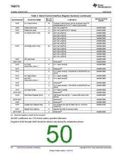
TAS5715
www.ti.com
SLOS645 –AUGUST 2010
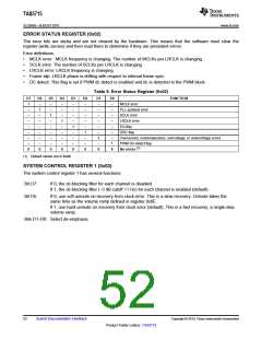
Table 7. System Control Register 1 (0x03)
D7
0
1
–
–
–
–
–
–
–
–
–
–
D6
–
–
0
–
–
–
–
–
–
–
–
–
D5
–
–
–
0
1
–
–
–
–
–
–
–
D4
–
–
–
–
–
1
–
–
–
–
–
–
D3
–
–
–
–
–
–
0
–
–
–
–
–
D2
–
–
–
–
–
–
–
0
–
–
–
–
D1
–
–
–
–
–
–
–
–
0
0
1
1
D0
–
–
–
–
–
–
–
–
0
1
0
1
FUNCTION
PWM high-pass (dc blocking) disabled
(1)
PWM high-pass (dc blocking) enabled
(1)
Reserved
Soft unmute on recovery from clock error
(1)
Hard unmute on recovery from clock error
(1)
Reserved
(1)
Reserved
Reserved(1)
(1)
No de-emphasis
De-emphasis for fS = 32 kHz
De-emphasis for fS = 44.1 kHz
De-emphasis for fS = 48 kHz
(1) Default values are in bold.
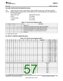
SERIAL DATA INTERFACE REGISTER (0x04)
As shown in Table 8, the TAS5715 supports nine serial data modes. The default is 24-bit, I2S mode.
Table 8. Serial Data Interface Control Register (0x04) Format
RECEIVE SERIAL DATA
INTERFACE FORMAT
WORD
LENGTH
D7–D4
D3
D2
D1
D0
Right-justified
16
20
24
16
20
24
16
20
24
0000
0000
0000
000
0
0
0
0
0
0
0
0
1
1
1
1
1
1
1
1
0
0
0
0
1
1
1
1
0
0
0
0
1
1
1
1
0
0
1
1
0
0
1
1
0
0
1
1
0
0
1
1
0
1
0
1
0
1
0
1
0
1
0
1
0
1
0
1
Right-justified
Right-justified
I2S
I2S
0000
0000
0000
0000
0000
0000
0000
0000
0000
0000
0000
0000
(1)
I2S
Left-justified
Left-justified
Left-justified
Reserved
Reserved
Reserved
Reserved
Reserved
Reserved
Reserved
(1) Default values are in bold.
Copyright © 2010, Texas Instruments Incorporated
Submit Documentation Feedback
53
Product Folder Link(s): TAS5715

 TI [ TEXAS INSTRUMENTS ]