TAS5715
SLOS645 –AUGUST 2010
www.ti.com
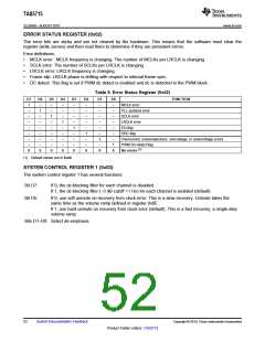
ERROR STATUS REGISTER (0x02)
The error bits are sticky and are not cleared by the hardware. This means that the software must clear the
register (write zeroes) and then read them to determine if they are persistent errors.
Error definitions:
•
•
•
•
•
MCLK error : MCLK frequency is changing. The number of MCLKs per LRCLK is changing.
SCLK error: The number of SCLKs per LRCLK is changing.
LRCLK error: LRCLK frequency is changing.
Frame slip: LRCLK phase is drifting with respect to internal frame sync.
DC detect: This flag is set if PWM dc detect is enabled and dc is detected in the PWM block.
Table 6. Error Status Register (0x02)
D7
1
D6
–
D5
–
D4
–
D3
–
D2
–
D1
–
D0
–
FUNCTION
MCLK error
PLL autolock error
SCLK error
LRCLK error
EQ flag
–
1
–
–
–
–
–
–
–
–
1
–
–
–
–
–
–
–
–
1
–
–
–
–
–
–
–
–
1
–
–
–
–
–
–
–
–
1
–
–
DRC flag
–
–
–
–
–
–
1
–
Overcurrent, overtemperature, overvoltage, or undervoltage errors
PWM DC-detect flag
–
–
–
–
–
–
–
1
(1)
0
0
0
0
0
0
0
0
No errors
(1) Default values are in bold.
SYSTEM CONTROL REGISTER 1 (0x03)
The system control register 1 has several functions:
Bit D7:
Bit D5:
If 0, the dc-blocking filter for each channel is disabled.
If 1, the dc-blocking filter (–3 dB cutoff <1 Hz) for each channel is enabled (default).
If 0, use soft unmute on recovery from clock error. This is a slow recovery. Unmute takes the
same time as the volume ramp defined in register 0x0E.
If 1, use hard unmute on recovery from clock error (default). This is a fast recovery, a single-step
volume ramp.
Bits D1–D0: Select de-emphasis
52
Submit Documentation Feedback
Copyright © 2010, Texas Instruments Incorporated
Product Folder Link(s): TAS5715

 TI [ TEXAS INSTRUMENTS ]