TAS5727
www.ti.com
SLOS670 –NOVEMBER 2010
SERIAL INTERFACE CONTROL AND TIMING
I2S Timing
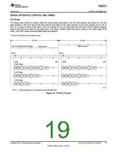
I2S timing uses LRCLK to define when the data being transmitted is for the left channel and when it is for the
right channel. LRCLK is low for the left channel and high for the right channel. A bit clock running at 32, 48, or
64 × fS is used to clock in the data. There is a delay of one bit clock from the time the LRCLK signal changes
state to the first bit of data on the data lines. The data is written MSB-first and is valid on the rising edge of bit
clock. The DAP masks unused trailing data bit positions.
2-Channel I2S (Philips Format) Stereo Input
32 Clks
32 Clks
LRCLK (Note Reversed Phase)
Right Channel
Left Channel
SCLK
SCLK
MSB
LSB
MSB
LSB
24-Bit Mode
23 22
9
5
1
8
4
0
5
1
4
1
0
23 22
19 18
15 14
9
5
1
8
4
0
5
1
4
0
1
0
20-Bit Mode
19 18
0
16-Bit Mode
15 14
T0034-01
NOTE: All data presented in 2s-complement form with MSB first.
Figure 16. I2S 64-fS Format
Copyright © 2010, Texas Instruments Incorporated
Submit Documentation Feedback
19
Product Folder Link(s): TAS5727

 TI [ TEXAS INSTRUMENTS ]