TAS5727
www.ti.com
SLOS670 –NOVEMBER 2010
I2C CHIP SELECT
A_SEL_FAULT is an input pin during power up. It can be pulled high (15-kΩ pullup) or low (15-kΩ pulldown).
High indicates an I2C subaddress of 0x56, and low a subaddress of 0x54.
I2C Device Address Change Procedure
•
•
•
Write to device address change enable register, 0xF8 with a value of 0xF9A5 A5A5.
Write to device register 0xF9 with a value of 0x0000 00XX, where XX is the new address.
Any writes after that should use the new device address XX.
SINGLE-FILTER PBTL MODE
The TAS5727 supports parallel BTL (PBTL) mode with OUT_A/OUT_B (and OUT_C/OUT_D) connected before
the LC filter. In order to put the part in PBTL configuration, drive PBTL (pin 8) HIGH. This synchronizes the
turnoff of half-bridges A and B (and similarly C/D) if an overcurrent condition is detected in either half-bridge.
There is a pulldown resistor on the PBTL pin that configures the part in BTL mode if the pin is left floating.
PWM output multiplexers should be updated to set the device in PBTL mode. Output Mux Register (0x25) should
be written with a value of 0x0110 3245. Also, the PWM shutdown register (0x19) should be written with a value
of 0x3A.
DEVICE PROTECTION SYSTEM
Overcurrent (OC) Protection With Current Limiting
The device has independent, fast-reacting current detectors on all high-side and low-side power-stage FETs. The
detector outputs are closely monitored by two protection systems. The first protection system controls the power
stage in order to prevent the output current further increasing, i.e., it performs a cycle-by-cycle current-limiting
function, rather than prematurely shutting down during combinations of high-level music transients and extreme
speaker load-impedance drops. If the high-current condition situation persists, i.e., the power stage is being
overloaded, a second protection system triggers a latching shutdown, resulting in the power stage being set in
the high-impedance (Hi-Z) state. The device returns to normal operation once the fault condition (i.e., a short
circuit on the output) is removed. Current-limiting and overcurrent protection are not independent for half-bridges.
That is, if the bridge-tied load between half-bridges A and B causes an overcurrent fault, half-bridges A, B, C,
and D are shut down.
Overtemperature Protection
The TAS5727 has an overtemperature-protection system. If the device junction temperature exceeds 150°C
(nominal), the device is put into thermal shutdown, resulting in all half-bridge outputs being set in the
high-impedance (Hi-Z) state and A_SEL_FAULT being asserted low. The TAS5727 recovers automatically once
the temperature drops approximately 30°C.
Undervoltage Protection (UVP) and Power-On Reset (POR)
The UVP and POR circuits of the TAS5727 fully protect the device in any power-up/down and brownout situation.
While powering up, the POR circuit resets the overload circuit (OLP) and ensures that all circuits are fully
operational when the PVDD and AVDD supply voltages reach 7.6 V and 2.7 V, respectively. Although PVDD and
AVDD are independently monitored, a supply-voltage drop below the UVP threshold on AVDD or either PVDD
pin results in all half-bridge outputs immediately being set in the high-impedance (Hi-Z) state and A_SEL_FAULT
being asserted low.
FAULT INDICATION
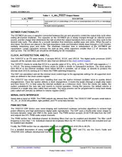
A_SEL_FAULT is an input pin during power up. This pin can be programmed after RESET to be an output by
writing 1 to bit 0 of I2C register 0x05. In that mode, the A_SEL_FAULT pin has the definition shown in Table 1.
Any fault resulting in device shutdown is signaled by the A_SEL_FAULT pin going low (see Table 1). A latched
version of this pin is available on D1 of register 0x02. This bit can be reset only by an I2C write.
Copyright © 2010, Texas Instruments Incorporated
Submit Documentation Feedback
17
Product Folder Link(s): TAS5727

 TI [ TEXAS INSTRUMENTS ]