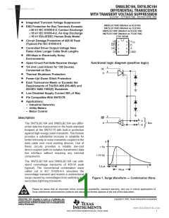
ꢀ ꢁꢂ ꢃꢄ ꢅ ꢆ ꢇꢈ ꢉꢊ ꢀꢁꢋ ꢃ ꢄ ꢅꢆꢇ ꢈ ꢉ
ꢚ
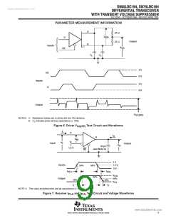
ꢌ ꢍ ꢎ ꢏꢐ ꢏꢁ ꢑ ꢍ ꢒꢄ ꢑꢐ ꢒꢁ ꢀꢆ ꢏꢍ ꢓ ꢏ ꢐ
www.DꢎataSheet4U.com
ꢔꢍ ꢑ ꢕ ꢑ ꢐ ꢒꢁ ꢀꢍ ꢏꢁ ꢑ ꢓ ꢖꢄꢑꢒꢗ ꢏ ꢀ ꢘꢙ ꢙꢐ ꢏꢀ ꢀꢍ ꢖ ꢁ
SLLS236F − OCTOBER 1996 − REVISED APRIL 2005
†
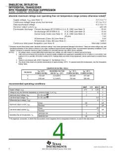
absolute maximum ratings over operating free−air temperature range (unless otherwise noted)
Supply voltage, V
(see Note 1) . . . . . . . . . . . . . . . . . . . . . . . . . . . . . . . . . . . . . . . . . . . . . . . . . . . . −0.5 V to 7 V
CC
Continuous voltage range at any bus terminal . . . . . . . . . . . . . . . . . . . . . . . . . . . . . . . . . . . . . . . . . −15 V to 15 V
Data input/output voltage . . . . . . . . . . . . . . . . . . . . . . . . . . . . . . . . . . . . . . . . . . . . . . . . . . . . . . . . . . . −0.3 V to 7 V
Receiver output current, I . . . . . . . . . . . . . . . . . . . . . . . . . . . . . . . . . . . . . . . . . . . . . . . . . . . . . . . . . . . . . . . 20 mA
O
Electrostatic discharge: Contact discharge (IEC61000-4-2) A, B, GND (see Note 2) . . . . . . . . . . . . . . . 30 kV
Air discharge (IEC61000-4-2)
A, B, GND (see Note 2) . . . . . . . . . . . . . . . 15 kV
Human body model (see Note 3) A, B, GND (see Note 2) . . . . . . . . . . . . . . . 15 kV
All pins . . . . . . . . . . . . . . . . . . . . . . . . . . . . . . 3 kV
All terminals (Class 3A) (see Note 2) . . . . . . . . . . . . . . . . . . . . . . . . . . . . . . . . . . . . 8 kV
All terminals (Class 3B) (see Note 2) . . . . . . . . . . . . . . . . . . . . . . . . . . . . . . . . . . 1200 V
Continuous total power dissipation (see Note 4) . . . . . . . . . . . . . . . . . . . . . . . . . . . . . . . . . . . . . Internally Limited
†
Stresses beyond those listed under “absolute maximum ratings” may cause permanent damage to the device. These are stress ratings only, and
functional operation of the device at these or any other conditions beyond those indicated under “recommended operating conditions” is not
implied. Exposure to absolute-maximum-rated conditions for extended periods may affect device reliability.
NOTES: 1. All voltage values, except differential input/output bus voltage, are with respect to network ground terminal.
2. GND and bus terminal ESD protection is beyond readily available test equipment capabilities for IEC 61000-4-2, EIA/JEDEC test
method A114-A and MIL-STD-883C method 3015. Ratings listed are limits of test equipment; device performance exceeds these
limits.
3. Tested in accordance with JEDEC Standard 22, Test Method A114-A.
4. The driver shuts down at a junction temperature of approximately 160°C. To operate below this temperature, see the Dissipation
Rating Table.
DISSIPATION RATING TABLE
T
≤ 25°C
DERATING FACTOR
T
= 70_C = 85_C
T
A
A
A
PACKAGE
POWER RATING
ABOVE T = 25°C
POWER RATING POWER RATING
A
D
P
725 mW
5.8 mW/°C
9.2 mW/°C
464 mW
736 mW
377 mW
598 mW
1150 mW
recommended operating conditions
‡
MIN
TYP
MAX
5.25
12
UNIT
V
Supply voltage, V
CC
4.75
−7
2
5
Voltage at any bus terminal (separately or common mode), V or V
IC
V
I
High-level input voltage, V
IH
D, DE, and RE
D, DE, and RE
V
Low-level input voltage, V
IL
0.8
12
V
Differential input voltage, |V
ID
|
V
Driver
−60
−8
mA
mA
High-level output current, I
OH
OL
Receiver
Driver
60
4
Low-level output current, I
mA
Receiver
SN75LBC184
SN65LBC184
0
70
85
°C
°C
Operating free-air temperature, T
A
−40
‡
The algebraic convention, in which the less-positive (more-negative) limit is designated minimum, is used in this data sheet.
4
POST OFFICE BOX 655303 • DALLAS, TEXAS 75265

 TI [ TEXAS INSTRUMENTS ]