ꢀꢁ ꢂꢃ ꢄ ꢅꢆꢇ ꢈ ꢉ ꢊ ꢀꢁ ꢋꢃ ꢄꢅ ꢆꢇ ꢈꢉ
ꢌꢍ ꢎꢎ ꢏꢐ ꢏꢁꢑ ꢍꢒ ꢄ ꢑ ꢐꢒꢁ ꢀꢆ ꢏ ꢍꢓ ꢏ ꢐ
ꢔ ꢍꢑ ꢕ ꢑ ꢐꢒꢁꢀ ꢍꢏꢁ ꢑ ꢓꢖ ꢄꢑꢒꢗ ꢏ ꢀꢘ ꢙꢙꢐ ꢏꢀ ꢀ ꢍꢖ ꢁ
ꢚ
www.DataSheet4U.com
SLLS236F − OCTOBER 1996 − REVISED APRIL 2005
PARAMETER MEASUREMENT INFORMATION
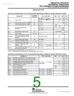
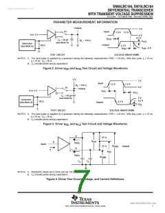
Output
3 V
0 V
S1
Input
1.5 V 1.5 V
0 or 3 V
0.5 V
t
PZH
C
= 50 pF
R
= 110 Ω
L
L
V
OH
(see Note B)
Generator
(see Note A)
Output
50 Ω
2.3 V
V
off
≈ 0 V
t
PHZ
TEST CIRCUIT
VOLTAGE WAVEFORMS
NOTES: A. The input pulse is supplied by a generator having the following characteristics: PRR = 1.25 kHz, 50% duty cycle, t ≤ 10 ns,
r
t ≤ 10 ns, Z = 50 Ω.
f
O
B.
C
includes probe and jig capacitance.
L
Figure 2. Driver t
and t
Test Circuit and Voltage Waveforms
PZH
PHZ
5 V
3 V
0 V
Input
1.5 V
1.5 V
R
= 110 Ω
L
S1
Output
0 or 3 V
t
PZL
t
PLZ
C
= 50 pF
L
5 V
0.5 V
(see Note B)
Generator
(see Note A)
50 Ω
2.3 V
Output
V
OL
TEST CIRCUIT
VOLTAGE WAVEFORMS
NOTES: A. The input pulse is supplied by a generator having the following characteristics: PRR = 1.25 kHz, 50% duty cycle, t ≤ 10 ns,
r
t ≤ 10 ns, Z = 50 Ω.
f
O
B.
C
includes probe and jig capacitance.
L
Figure 3. Driver t
and t
Test Circuit and Voltage Waveforms
PZL
PLZ
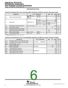
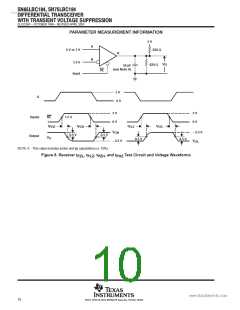
A
27 Ω
V
OD
D
I
I
O(A)
Input
V
O(A)
27 Ω
Output
B
I
I
V
OC
O(B)
C
V
O(B)
C
L
L
NOTES: A. Resistance values are in ohms and are 1% tolerance.
B. includes probe and jig capacitance.
C
L
Figure 4. Driver Test Circuit, Voltage, and Current Definitions
7
POST OFFICE BOX 655303 • DALLAS, TEXAS 75265

 TI [ TEXAS INSTRUMENTS ]