Application Notes
PT6920/PT6930 Series
Adjusting the Output Voltage of the PT6920 and
PT6930 Dual Output Voltage ISRs
5. If Vo1 is increased above 3.3V, the minimum input voltage
to the ISR must also be increased. The minimum
required input voltage must be (Vo1 + 1.2)V or 4.5V,
whichever is greater. Do not exceed 5.5V
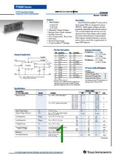
Each output voltage from the PT6920 and PT6930 series
of ISRs can be independantly adjusted higher or lower than
the factory trimmed pre-set voltage. Vo1 or Vo2 may each
be adjusted either up or down using a single external resis-
6. Never connect capacitors to either the Vo1 Adjust or Vo2
Adjust pins. Any capacitance added to these control pins
will affect the stability of the respective regulated output.
2
tor . Table 1 gives the adjustment range for both Vo1 and
Vo2 for each model in the series as Va(min) and Va(max).
7. Adjusting either voltage (Vo1 or Vo2) may increase the
power dissipation in the regulator, and correspondingly
change the maximum current available at either output.
Consult the factory for application assistance.
3
Note that Vo2 must always be lower than Vo1
.
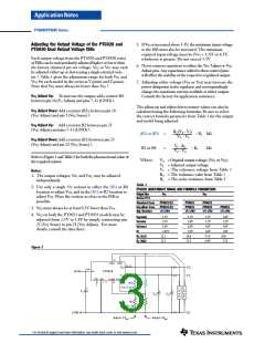
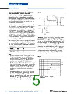
Vo1 Adjust Up: To increase the output, add a resistor R4
2
between pin 16 (V1 Adjust) and pins 7-11 (GND) .
The adjust up and adjust down resistor values can also be
calculated using the following formulas. Be sure to select
the correct formula parameter from Table 1 for the output
and model being adjusted.
Vo1 Adjust Down: Add a resistor (R3), between pin 16
(Vo1 Adjust) and pin 1 (Vo1 Sense) .
2
Vo2 Adjust Up: Add a resistor R2 between pin 23
2
(Vo2 Adjust) and pins 7-11 (GND) .
Ro (Va – Vr)
Vo – Va
(R1) or (R3)
=
=
– Rs kΩ
Vo2 Adjust Down: Add a resistor (R1) between pin 23
2
(Vo2 Adjust) and pin 22 (Vo2 Sense) .
Vr . Ro
Va – Vo
R2 or R4
Where:
– Rs
kΩ
Refer to Figure 1 and Table 2 for both the placement and value of
the required resistor.
Vo = Original output voltage, (Vo1 or Vo2)
Va = Adjusted output voltage
Vr = The reference voltage from Table 1
Ro = The resistance value from Table 1
Rs = The series resistance from Table 1
Notes:
1. The output voltages, Vo1 and Vo2, may be adjusted
independantly.
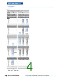
Table 1
PT6920 ADJUSTMENT RANGE AND FORMULA PARAMETERS
2. Use only a single 1% resistor in either the (R3) or R4
location to adjust Vo1, and in the (R1) or R2 location to
adjust Vo2. Place the resistor as close to the ISR as
possible.
Output Bus
Series Pt #
Vo1
Vo2
Standard Case
Excalibur Case
Adj. Resistor
PT6921/22
PT6931/32
(R3)/R4
PT6921
PT6931
(R1)/R2
PT6922
PT6932
(R1)/R2
PT6933
(R1)/R2
3. Vo2 must always be at least 0.2V lower than Vo1.
4. Vo2 on both the PT6921 and PT6931 models may be
adjusted from 2.5V to 1.8V by simply connecting pin
22 (Vo2 Sense) to pin 23 (Vo2 Adjust). For more
details, consult the data sheet.
V (nom)
o
3.3V
2.3V
3.6V
1.02V
12.1
2.5V
1.8V
3.0V
1.0V
10.0
1.5V
1.2V
3.0V
1.0V
9.76
6.49
1.8V
1.2V
3.0V
1.0V
10.0
Va(min)
Va(max)
Vr
R
R
(kΩ)
(kΩ)
o
s
12.1
11.5
3.32
Figure 1
22
V2(sns)
1
V1(sns)
18
12
-
-
21
15
V2out
V2o
V1o
4,5,6
Vin
Vin
PT6920
V1out
GND
7
Vo2(adj) Vo1(adj)
23 16
STBY
3
- 11
(R3)
(R1)
R2
Adj Down
L
O
A
D
L
O
A
D
+
+
+
C1
C2
C3
R4
Adjust Up
COM
CO
Adjust V1out
Adjust V2out
For technical support and more information, see inside back cover or visit www.ti.com

 TI [ TEXAS INSTRUMENTS ]