Application Notes
PT6880 Series
Adjusting the Output Voltage of the PT6880
5-A Excalibur™ Converter Series
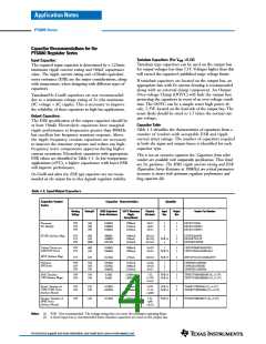
Figure 3-1
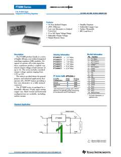
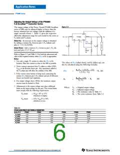
The output voltage of the Power Trends PT6880 Excalibur
series of ISRs may be adjusted higher or lower than the
factory trimmed pre-set voltage with the addition of a
18
1
single external resistor . Table 3-1 gives the respective
Vsense
allowable adjustment range for each model in the series as
Va (min) and Va (max).
8
–10
15 –17
Vin
Vo
Vin
PT6880
Vo
STBY
4
GND
6, 7,
Vo(adj)
1
Adjust Up: An increase in the output voltage is obtained
by adding a resistor R2, between pin 1 (Vo Adjust) and
pins 6, 7 /11-14 (GND).
11
– 14
(R1)
Adj Down
L
O
A
D
+
+
C in
Cout
Adjust Down: Add a resistor (R1), between pin 1 (Vo Ad-
just) and pins 15-17 (Vout).
R2
Adjust
Up
Refer to Figure 3-1 and Table 3-2 for both the placement and
value of the required resistor, either (R1) or R2 as appropriate.
C O M
C O M
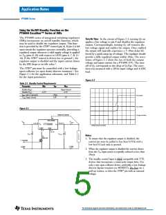
Notes:
1. Use only a single 1% resistor in either the (R1) or R2
location. Place the resistor as close to the ISR as possible.
The values of (R1) [adjust down], and R2 [adjust up], can
also be calculated using the following formulas.
2. Never connect capacitors from Vo adjust to either GND,
Vout, or the Remote Sense pin. Any capacitance added to
the Vo adjust pin will affect the stability of the ISR.
Ro (Vo – 1.25) (Va – 1.25)
(R1)
R2
=
=
– Rs kΩ
kΩ
1.25 (Vo – Va)
3. If the remote sense feature is being used, connecting the
resistor (R1) between pin 1 (Vo Adjust) and pin 18 (Remote
Sense) can benefit load regulation.
Ro (Vo – 1.25)
Va - Vo
– Rs
4. For output voltages above 10Vdc, the maximum output
current must be limited to 4Adc.
5. Adjustments to the output voltage may place additional
limits on the input voltage for the part. The revised limits
must comply with the following requirements.
Where: Vo = Original output voltage
Va = Adjusted output voltage
Ro = The resistance value in Table 3-1
Rs = The series resistance from Table 3-1
Vin (min)
= (Vout + 3)V or 15V,
whichever is higher.
Vin (max)
= (10 x Vout )V or 36V,
whichever is less.
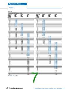
Table 3-1
PT6880 ADJUSTMENT AND FORMULA PARAMETERS
Series Pt #
PT6882
PT6881
PT6883
PT6884
PT6886
PT6885
Vo (nom)
Va (min)
Va (max)
Ro (kΩ)
Rs (kΩ)
2.5V
1.8V
4.3V
4.99
2.49
3.3V
2.2V
4.7V
4.22
4.99
5.0V
3.0V
6.5V
2.49
4.99
9.0V
6.0V
10.2V
2.0
12.0V
9.0V
13.6V
2.0
15.0V
10.0V
17.0V
2.0
12.7
12.7
12.7
For technical support and more information, see inside back cover or visit www.ti.com

 TI [ TEXAS INSTRUMENTS ]