Application Notes
PT3320/3340/4560/4580 Series
Adjusting the Output Voltage of Power Trends’
30W Isolated DC/DC Converter Series
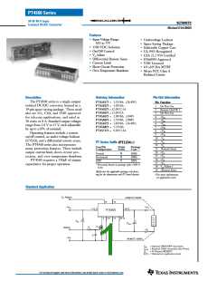
The factory pre-set output voltage of Power Trends’ 30W
series of isolated DC/DC converters may be adjusted
within a nominal 10ꢀ range. This is accomplished with
the addition of a single external resistor. For the input
voltage range specified in the data sheet, Table 1 gives the
allowable adjustment range for each model as Vo (min)
and Vo (max).
3. If the remote sense pins are not being used, the resistors
(R1) and R2 can be connected to +Vout or -Vout
respectively.
4. The adjusted output voltage, Va effectively sets the voltage
across pins 13 and 19 ( Remote Sense). When using the
remote sense pins, Vout (measured directly across pins 10–
12, and 14–17) can be significantly higher than Va, and may
exceed Vo (max). If Va is adjusted upward of Vo(max), the
the minimum input voltage is increased by the same
percentage as Vout exceeds Vo(max).
Adjust Up: An increase in the output voltage is obtained
by adding a resistor, R2 between Vo adjust (pin 18), and
-Remote Sense (pin 13). See note 4.
The values of (R1) [adjust down], and R2 [adjust up], can
also be calculated using the following formulas.
Adjust Down: Add a resistor (R1), between Vo adjust (pin
18), and +Remote Sense (pin 19).
Ko (Va – Vr)
Vr (Vo – Va)
(R1)
=
– Rs
kΩ
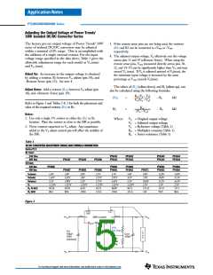
Refer to Figure 1 and Tables 2 & 3 for both the placement and
value of the required resistor, (R1) or R2.
Ko
(Va – Vo)
R2
=
– Rs
kΩ
Notes:
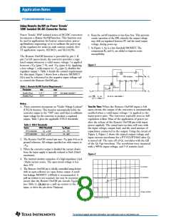
1. Use only a single 1ꢀ resistor in either the (R1) or R2
location. Place the resistor as close to the ISR as possible.
Where
Vo = Original output voltage
Va = Adjusted output voltage
2. Never connect capacitors to Vo adjust. Any capacitance
added to the Vo adjust control pin will affect the stability of
the ISR.
Vr = Reference voltage (Table 1)
Ko = Multiplier constant (Table 1)
Rs = Series resistance (Table 1)
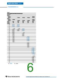
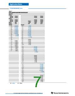
Table 1
DC/DC CONVERTER ADJUSTMENT RANGE AND FORMULA PARAMETERS
Series Pt #
AL Case:
24V Bus
48V Bus
CU Case:
PT3341
PT3321
PT3342
PT3322
PT3343
PT3323
PT3344
PT3324
PT3327
PT4567
PT3325
PT4565
PT3326
PT4566
24V Bus
48V Bus
PT4585
PT4581
PT4561
PT4582
PT4562
PT4583
PT4563
PT4584
PT4564
PT4571
Vo(nom)
Vo(min)
Vo(max)
Vr
1.8V
1.62V
2.5V
1.225V
69.58
80.6
1.8V
2.0V
1.8V
2.2V
1.225V
62.47
150.0
2.5V
3.3V
5.0V
4.5V
5.5V
1.225V
68.71
121.0
9.0V
7.0V
10.0V
2.5V
133.25
110
12.0V
10.8V
13.2V
2.5V
135.9
90.9
15.0V
13.5V
16.5V
2.5V
137.5
80.6
1.62V
1.98V
1.225V
69.58
80.6
2.25V
2.75V
1.225V
42.33
121.0
2.95V
3.65V
1.225V
68.89
150.0
Ko (V·kΩ)
Rs (kΩ)
Figure 1
2
19
Remote
On/Off
Sns(+)
7, 8,
9
14 - 17
+Vin
+Vout
+V in
30W Isolated
+Vout
-Vin
4, 5,
-Vout
10
Sns(-)
13
Vo(adj)
18
6
- 12
(R1)
Adj Down
L
O
A
D
Cin
100
100V
(Optional)
+
+
µ
F
Cout
330µF
R2
Adj
Up
-Vin
-Vout
For technical support and more information, see inside back cover or visit www.ti.com

 TI [ TEXAS INSTRUMENTS ]