Application Notes
PT3320/3340/4560/4580 Series
Using Remote On/Off on Power Trends’
30W Isolated DC-DC Converter Series
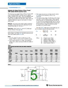
Power Trends’ 30W isolated series of DC/DC converters
incorporate a Remote On/Off function. This function may
be used in applications for battery conservation, power-
up/shutdown sequencing, or to co-ordinate the power-up
of the regulator for active in-rush current control. (See
TI application reports, SLTA021, and SLUA250).
6. Keep the on/off transition to less than 1ms. This prevents
erratic operation of the ISR, whereby the output voltage
may drift un-regulated between 0V and the rated output
voltage during power-up.
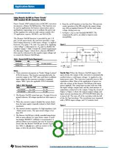
7. In Figure 1, Q1 is a low-threshold MOSFET. The
components R1 and C1 are added to improve noise
susceptibility.
The Remote On/Off function is provided by pin 2. If
pin 2 is left open-circuit, the converter provides a regu-
1
lated output whenever a valid source voltage is applied
Figure 1
between +Vin (pins 7-9), and –Vin (pins 4-6). Applying
a low voltage 2, with respect to –Vin (pin 2), disables the
regulator output 3. Table 1 details the control requirements
for this input. Figure 1 shows how a discrete MOSFET
(Q1) may be referenced to the negative input voltage rail
to control the Remote On/Off pin.
2
1 9
Remote
On/Off
Sns(+)
7, 8,
9
14 - 17
+Vin
+Vout
+Vin
30W Isolated
+Vo
-Vin
-Vout
10
Sns(-)
1 3
Vo(adj)
1 8
4, 5,
6
- 12
+
+
Cin
Cout
Q1
BSS138
Table 1 Remote On/Off Control Requirements 2
C1
0.01µF
Parameter
min
max
-Vin
–Vo
5
4
Enable (VIH
Disable (VIL
)
)
2.5V
15V (or open circuit)
0.8V
–0.3V
R1
,
10k
R1 & C1 -See Note 7
OFF/ ON
Notes:
1. These converters incorporate an “Under Voltage Lockout”
(UVLO) function. This function automatically holds the
converter output in the “Off” state until there is sufficient
input voltage for the converter to produce a regulated
output. Table 2 gives the applicable UVLO thresholds.
Turn-On Time: When the Remote On/Off input is left
open-circuit, the output of the converter is automatically
1
enabled when a valid input voltage is applied to the
input power pins. The converter typically rises to full
regulation within 30ms of the application of power (or
after the release of the Remote On/Off pin with input
power applied). The actual turn-on time will vary with
the input voltage, output load, and the total amount of
capacitance connected to the output. Using the circuit of
Figure 1, Figure 2 shows the typical output voltage and
input current waveforms for a PT3322/PT4562 after Q1
is turned off. The turn off of Q1 correlates with the fall
of the Q1 Vgs waveform. The waveforms were measured
with a 48Vdc input voltage, and 5-A resistive load.
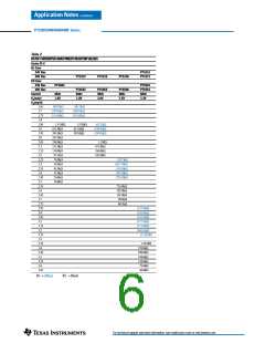
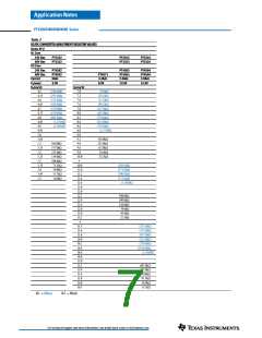
Table 2 UVLO Thresholds
Series
UVLO Threshold
Vin Range
PT3320/4560
PT3340/4580
34 2.0V
16.5 1.5V
36 – 75V
18 – 60V
2. The Remote On/Off control pin uses –Vin (pins 4-6) as its
ground reference. All voltages specified are with respect to
–Vin.
3. When the converter output is disabled the current drawn
from the input supply is typically reduced to 8mA (16mA
maximum).
Figure 2
4. The internal circuitry comprises of a high impedance (3µA
-10µA) current source. The open-circuit voltage is less
than 10V.
Vo (2V/Div)
5. The Remote On/Off pin is ideally controlled using devices
with an open-collector (or open-drain) output. A small
low-leakage MOSFET (<100nA) is recommended. A
pull-up resistor is not required, but may be necessary to
ensure that the Remote On/Off pin exceeds VIH(min)
(see Table 1). Do not use a pull-up resistor to the +Vin
input, or drive the pin above VIH(max).
Iin (0.5A/Div)
Q1Vgs (10V/Div)
HORIZ SCALE: 2ms/Div
For technical support and more information, see inside back cover or visit www.ti.com

 TI [ TEXAS INSTRUMENTS ]