PGA281
www.ti.com
SBOS664A –MARCH 2013–REVISED JUNE 2013
SAR ADC Driver
An example of the PGA281 used as a SAR ADC driver with the THS4031 used as input buffers to maximize
SNR and THD is shown in Figure 50 .
Buffering
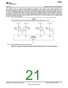
RC
Low-Pass
Filter
ADC-Side
Filtering
RB
RA
RA
THS4031
+
+
VOP
ADS8318
SAR ADC
CD
PGA281 VOCM
CA
RB
VON
+
THS4031
RC
Figure 50. SAR Driver with Input Buffer
Using TINA-TI™ SPICE-Based Analog Simulation Program with the PGA281
TINA is a simple, powerful, and easy-to-use circuit simulation program based on a SPICE engine. TINA-TI is a
free, fully functional version of the TINA software, preloaded with a library of macromodels in addition to a range
of both passive and active models. It provides all the conventional dc, transient, and frequency-domain analysis
of SPICE, as well as additional design capabilities.
Available as a free download from the Analog eLab Design Center, TINA-TI offers extensive post-processing
capability that allows users to format results in a variety of ways.
Virtual instruments offer users the ability to select input waveforms and probe circuit nodes, voltages, and
waveforms, creating a dynamic quick-start tool.
NOTE
NOTE: These files require that either the TINA software (from DesignSoft) or TINA-TI
software be installed. Download the free TINA-TI software from the TINA-TI folder.
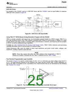
Two-Terminal Programmable Logic Controller
The circuit in Figure 51 is used to convert inputs of ±10 V, ±5 V, or ±20 mA to an output voltage range from 0 V
to 5 V. The input selection depends on the settings of the switch and the PGA281 gain. Further explanation, as
well as the TINA-TI simulation circuit, is provided in the compressed file that can be downloaded at the following
link: PGA281 PLC Circuit.
±10 V, ±5 V,
or ±20 mA
+
VOP
2.5 V
VOCM
PGA281
VON
250 ꢀ
µC
Figure 51. Two-Terminal, Programmable Logic Controller (PLC) Input
Copyright © 2013, Texas Instruments Incorporated
Submit Documentation Feedback
25
Product Folder Links: PGA281

 TI [ TEXAS INSTRUMENTS ]