PCM9211
www.ti.com
SBAS495 –JUNE 2010
APPLICATION INFORMATION
TYPICAL CIRCUIT CONNECTION
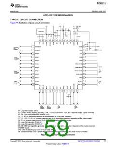
Figure 44 illustrates a typical circuit connection.
+5V
0V
+3.3V
0V
0V
COAX Input
C7
C8
C9
X1
Analog Input
C5
R3
R1
C6
R2
C3
C4
C1
C2
C10
48
47
46
45
44
43
42
41
40
39
38
37
C12
1
36
VDDRX
+3.3V
ERROR/ INT0
NPCM/ INT1
MPIO_A0
Interruption
Flag
Functions
R4
C11
2
3
4
5
6
7
8
9
35
34
33
32
31
30
29
28
COAX Input
RXIN1
RST
MPIO_A1
MPIO_A2
MPIO_A3
MPIO_C0
MPIO_C1
MPIO_C2
MPIO_C3
MPIO_B0
MPIO_B1
RXIN2
RXIN3
MPIO_A
Assigned
Functions
RXIN4/ASCKIO
RXIN5/ ABCKIO
RXIN6/ ALRCKIO
RXIN7/ ADIN0
MODE
Optical
Inputs
or
PCM
Audio
I/ F
MPIO_C
Assigned
Functions
10
11
12
27
26
25
0V or 3.3V
MS/ ADR1
MPIO_B
Assigned
Functions
Serial
Control
I/ F
MC/ SCL
13
14
15
16
17
18
19
20
21
22
23
24
C13
0V
+3.3V
MPIO_B
Assigned
Functions
MPOx
Assigned
Functions
PCM
Audio
I/ F
Serial
Control
I/ F
R1: Loop filter resistor, 680 Ω.
R2: Current-limiting resistor; generally, a 100-Ω to 500-Ω resistor is used, but it depends on the crystal resonator.
R3, R4: Coax input termination resisters, 75 Ω.
C1, C2: 4.7-mF electrolytic capacitor is recommended for 3-Hz cutoff frequency.
C3, C7, C12, C13: 0.1-mF ceramic capacitor and 10-mF electrolytic capacitor, depending on the power supply.
C4: 0.1-mF ceramic capacitor and 10-mF electrolytic capacitor is recommended.
C5: Loop filter capacitor, 0.068 mF.
C6: Loop filter capacitor, 0.0047 mF.
C8, C9: OSC load capacitor; generally, a 10-pF to 30-pF capacitor is used, but it depends on the crystal resonator
and PCB layout.
C10, C11: DC blocking capacitor for coax input, 0.1 mF.
X1: Crystal resonator. Use a 24.576-MHz fundamental resonator when the XTI clock source is needed.
Figure 44. Typical Circuit Connection
Copyright © 2010, Texas Instruments Incorporated
Submit Documentation Feedback
59
Product Folder Link(s): PCM9211

 TI [ TEXAS INSTRUMENTS ]