PCM9211
SBAS495 –JUNE 2010
www.ti.com
Digital Audio Interface Transmitter
Overview
The PCM9211 has an onboard Digital Audio Interface Transmitter (DIT) that transmits S/PDIF data from 7 kHz to
216 kHz, up to 24-bit audio data. The first 48 bits of the channel status buffer are programmable. The source for
the DIT is selectable from the built-in routing function of the PCM9211 as well as the dedicated inputs assigned
to the MPIOs.
Selection OF DIT Input Source
Selection of the DIT audio and clock sources is done using the Registers 60h/TXSSRC[2:0] and
60h/TXPSRC[2:0]. The system clock source for the DIT is selected using the Register 60h/TXSSRC[2:0]. The
PCM audio data source for the DIT (BCK. LRCK, and Data) is selected using the Register 60h/TXPSRC[2:0].
The DIT can also be operated in a standalone mode. In standalone mode, the data source is provided through
MPIO_C. See the DIT Stand-Alone section for more details.
DIT Output Biphase
The S/PDIF-encoded signal generated by the DIT module is available through the MPO0 and MPO1 pins. The
MPO selection registers (Register 78h/MPOxSEL[3:0]) can be set to '1101' to determine the DIT output through
one of these two pins.
In addition to the standard MPOx pins, the DIT output can also be multiplexed to the RECOUT pin, or back into
the DIR. An example of where this multiplexing might occur is in a jitter cleaner application. The DIR in the
PCM9211 has excellent jitter reduction. Data can be brought in from an auxiliary source, transmitted through the
DIT internally, then routed to the DIR. This process, in turn, cleans the clocks and provides a stable, well-clocked
PCM source. This feature is especially useful for jittery sources, such as HDMI.
Audio Data and Clock
The DIT can accept a 128fS, 256fS, or 512fS system clock. The clock ratio selection is set by using the Register
TXSCK[2:0]. A 216-kHz sampling frequency is supported by using the 128fS or 256fS system clock ratio. A
108-kHz sampling frequency can be supported up to a 512fS clock ratio.
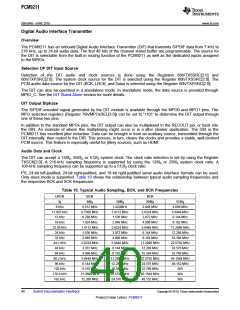
I2S, 24-bit left-justified, 24-bit right-justified, and 16-bit right-justified serial audio interface formats can be used.
Only slave mode is supported. Table 10 shows the relationship between typical audio sampling frequencies and
the respective BCK and SCK frequencies
Table 10. Typical Audio Sampling, BCK, and SCK Frequencies
LRCK
fS
BCK
SCK
64fS
128fS
256fS
512fS
4.096 MHz
5.6448 MHz
6.144 MHz
8.192 MHz
11.2896 MHz
12.288 MHz
16.384 MHz
22.5792 MHz
24.576 MHz
32.768 MHz
45.1584 MHz
49.152 MHz
N/A
8 kHz
0.512 MHz
0.7056 MHz
0.768 MHz
1.024 MHz
1.4112 MHz
1.536 MHz
2.048 MHz
2.8224 MHz
3.072 MHz
4.096 MHz
5.6448 MHz
6.144 MHz
8.192 MHz
11.2896 MHz
12.288 MHz
1.024MHz
2.048 MHz
2.8224 MHz
3.072 MHz
4.096 MHz
5.6448 MHz
6.144 MHz
8.192 MHz
11.2896 MHz
12.288 MHz
16.384 MHz
22.5792 MHz
24.576 MHz
32.768 MHz
45.1584 MHz
49.152 MHz
11.025 kHz
12 kHz
1.4112 MHz
1.536 MHz
2.048 MHz
2.8224 MHz
3.072 MHz
4.096 MHz
5.6448 MHz
6.144 MHz
8.192 MHz
11.2896 MHz
12.288 MHz
16.384 MHz
22.5792 MHz
24.576 MHz
16 kHz
22.05 kHz
24 kHz
32 kHz
44.1 kHz
48 kHz
64 kHz
88.2 kHz
96 kHz
128 kHz
176.4 kHz
192 kHz
N/A
N/A
40
Submit Documentation Feedback
Copyright © 2010, Texas Instruments Incorporated
Product Folder Link(s): PCM9211

 TI [ TEXAS INSTRUMENTS ]