PCM9211
www.ti.com
SBAS495 –JUNE 2010
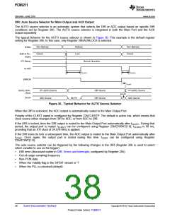
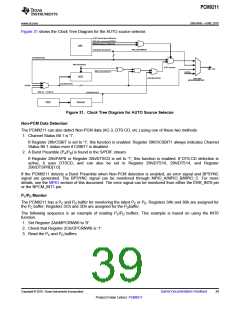
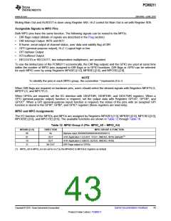
Figure 31 shows the Clock Tree Diagram for the AUTO source selector.
AUTO select signal defined by
REG.25h excluding AERROR.
ERROR defined by REG.25h
DIR
REG.26h/AERROR
SCK/BCK/LRCK/DOUT
SCK/BCK/LRCK
REG.40h/ADDIS
AUTO selector
Main Port
REG.42h/ADCKOUT
AUXINx
ADC
REG.26h/ACKSL
REG.6Bh/
MOSSRC&MOPSRC
SCK/BCK/LRCK
AUXINx
REG.42 h /ADCLK
SCK/BCK/LRCK
OSC
Divider
Figure 31. Clock Tree Diagram for AUTO Source Selector
Non-PCM Data Detection
The PCM9211 can also detect Non-PCM data (AC-3, DTS-CD, etc.) using one of these two methods:
1. Channel Status Bit 1 is '1'.
If Register 28h/CSBIT is set to '1', this function is enabled. Register 39h/SCSBIT1 always indicates Channel
Status Bit 1 status even if CSBIT1 is disabled.
2. A Burst Preamble (PA/PB) is found in the S/PDIF stream.
If Register 28h/PAPB or Register 28h/DTSCD is set to '1', this function is enabled. If DTS-CD detection is
active, it uses DTSCD, and can also be set in Register 29h/DTS16, 29h/DTS14, and Register
29h/DTSPRD[1:0].
If the PCM9211 detects a Burst Preamble when Non-PCM detection is enabled, an error signal and BPSYNC
signal are generated. The BPSYNC signal can be monitored through MPIO_A/MPIO_B/MPIO_C. For more
details, see the MPIO section of this document. The error signal can be monitored from either the ERR_INT0 pin
or the NPCM_INT1 pin.
PC/PD Monitor
The PCM9211 has a PC and PD buffer for monitoring the latest PC or PD. Registers 3Ah and 3Bh are assigned for
the PC buffer; Registers 3Ch and 3Dh are assigned for the PDbuffer.
The following sequence is an example of reading PC/PD buffers. This example is based on using the INT0
function.
1. Set Register 2Ah/MPCRNW0 to '0'.
2. Check that Register 2Ch/OPCRNW0 is '1'.
3. Read the PC and PD buffers.
Copyright © 2010, Texas Instruments Incorporated
Submit Documentation Feedback
39
Product Folder Link(s): PCM9211

 TI [ TEXAS INSTRUMENTS ]