ꢀ ꢁꢂ ꢃ ꢄ ꢅ ꢆꢇ ꢀꢁ ꢂ ꢃ ꢄ ꢅ ꢈ
ꢂ
ꢀ
ꢁ
ꢂ
ꢃ
ꢄ
ꢅ
ꢉꢇ
ꢀ
ꢁ
ꢃ
ꢄ
ꢅ
ꢄ
www.ti.com
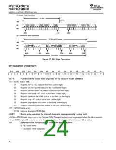
SLES081A − JUNE 2003 – REVISED MAY 2004
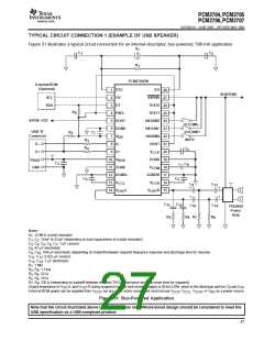
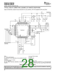
TYPICAL CIRCUIT CONNECTION 2 (EXAMPLE OF REMOTE HEADPHONE)
Figure 32 illustrates a typical circuit connection for a bus-powered, 100-mA headphone with seven HIDs.
C
+
9
Headphone
+
C
11
C
12
C
10
R
5
R
6
R
7
R
8
R
9
R
10
C
6
+
C
3
C
4
32 31 30 29 28 27 26 25
USB ’B’
Connector
R
2
C
5
1
2
3
4
5
6
7
8
24
23
22
21
20
19
18
17
PGND
V
V
BUS
D+
BUS
R
3
V
D+
CCP
HOST
D–
D–
PLAY/PAUSE
NEXT TRACK
R
4
FUNC3
V
GND
DD
PCM2706PJT
C
8
C
FUNC0
7
DGND
FUNC1
FUNC2
DOUT
MUTE
PREVIOUS TRACK
HID0/MS
HID1/MC
HID2/MD
VOLUME+
STOP
VOLUME–
External ROM
(Optional)
9
10 11 12 13 14 15 16
SDA
R
11
SUSPEND
SCL
R
1
X
1
C
1
C
2
Notes:
C
, C : 0.022-µF ceramic
11 12
X : 12-MHz crystal resonator
R : 1 MW
1
1
C , C : 10-pF to 33-pF (depending on load capacitance of crystal
R , R : 1.5 kW
1
2
2
11
resonator)
R , R : 22 W
3 4
C , C , C , C , C : 1-µF ceramic
R , R : 16 W
3
4
5
7
8
5
6
C : 47-µF electrolytic
R , R , R , R : 3.3 kW
6
7
8
9
10
C , C : 100-µF electrolytic (depending on required frequency
External ROM power can be supplied from V
, but any other active
, or V as a power source.
9
10
CCP
response)
componentmust not use V
, V
, V
CCP CCL CCR DD
Figure 32. Bus-Powered Application
Note that the circuit illustrated above is for information only. Whole board design should be considered to meet the
USB specification as a USB-compliant product.
28

 TI [ TEXAS INSTRUMENTS ]