ꢀꢁ ꢂꢃ ꢄ ꢅ ꢆ ꢇ ꢀ ꢁꢂ ꢃ ꢄꢅ ꢈ
ꢀꢁꢂ ꢃ ꢄ ꢅ ꢉ ꢇ ꢀ ꢁꢂ ꢃ ꢄꢅ ꢄ
www.ti.com
SLES081A − JUNE 2003 – REVISED MAY 2004
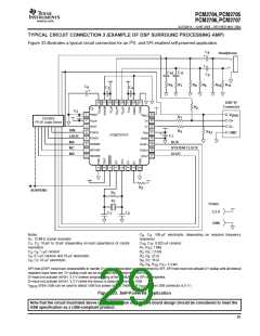
TYPICAL CIRCUIT CONNECTION 3 (EXAMPLE OF DSP SURROUND PROCESSING AMP)
2
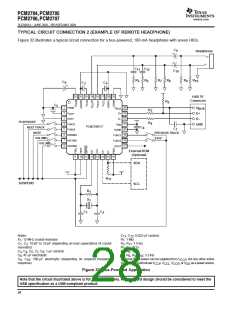
Figure 33 illustrates a typical circuit connection for an I S- and SPI-enabled self-powered application.
C
8
Headphone
+
+
C
10
C
11
C
9
R
6
R
7
R
8
R
9
R
10
R
11
C
6
+
C
3
C
4
32 31 30 29 28 27 26 25
USB ’B’
Connector
R
2
C
5
1
2
3
4
5
6
7
8
24
23
22
21
20
19
18
17
PGND
V
V
BUS
D+
BUS
R
R
3
TAS300X
I S I/F Audio Device
V
D+
CCP
2
HOST
D–
D–
DIN
4
R
12
FUNC3
V
GND
DD
+
PCM2707PJT
C
7
LRCK
MS
FUNC0
DGND
FUNC1
FUNC2
DOUT
BCK
HID0/MS
HID1/MC
HID2/MD
MC
SYSTEM CLOCK
DOUT
MD
9
10 11 12 13 14 15 16
R
5
SUSPEND
R
1
X
1
Power
3.3 V
C
C
2
1
GND
Notes:
X : 12-MHz crystal resonator
C , C : 100-µF electrolytic (depending on required frequency
8 9
response)
C , C : 0.022-µF ceramic
10 11
1
C , C : 10-pF to 33-pF (depending on load capacitance of crystal
1
2
resonator)
R , R : 1 MW
1
12
R , R : 1.5 kW
C , C : 1-µF ceramic
3
4
2
5
C : 0.1-µF ceramic and 10-µF electrolytic
R , R : 22 W
5
3 4
C , C : 47-µF electrolytic
R , R : 16 W
6 7
6
7
R , R , R , R : 3.3 kW
8
9
10 11
SPI host (DSP) must have responsibility to handle D+ pullup if descriptor is programmed by SPI. SPI host must not activate D+ pullup until all internal
registers have been set. D+ pullup must not be activated while detaching from host.
D+must not activate (HIGH: 3.3 V) before programming of the PCM2707 by SPI is completed.
D+must not activate (HIGH: 3.3 V) while the device is detached from the USB.
V
BUS
of the USB can be used to detect USB bus power status. (Note that V of the USB connector is 5 V.)
BUS
Figure 33. Self-Powered Application
Note that the circuit illustrated above is for information only. Whole board design should be considered to meet the
USB specification as a USB-compliant product.
29

 TI [ TEXAS INSTRUMENTS ]