ꢀ ꢁꢂ ꢃ ꢄ ꢅ ꢆ
www.ti.com
SLES080B – MAY 2003 – REVISED NOVEMBER 2003
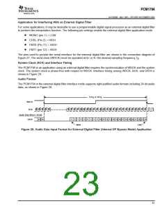
WDCK
50% of V
DD
DD
DD
t
t
t
(LB)
(BCH)
(BCL)
50% of V
50% of V
BCK
t
t
(BCY)
(BL)
DATA
t
t
(DS)
(DH)
PARAMETER
MIN
20
7
MAX UNITS
t
t
t
t
t
t
t
BCK pulse cycle time
ns
ns
ns
ns
ns
ns
ns
(BCY)
(BCL)
(BCH)
(BL)
BCK pulse duration, LOW
BCK pulse duration, HIGH
7
BCK rising edge to WDCK falling edge
WDCK falling edge to BCK rising edge
DATA setup time
5
5
(LB)
5
(DS)
DATA hold time
5
(DH)
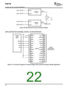
Figure 29. Audio Interface Timing for External Digital Filter (Internal DF Bypass Mode) Application
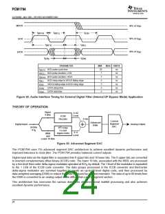
THEORY OF OPERATION
Upper
0–62
6 Bits
Level
ICOB
Decoder
0–66
Current
Segment
DAC
Advanced
DWA
Digital Input
Analog Output
24 Bits
8 f
rd
3 -Order
S
5-Level
Sigma-Delta
0–4
Level
MSB
and
Lower 18 Bits
Figure 30. Advanced Segment DAC
The PCM1794 uses TI’s advanced segment DAC architecture to achieve excellent dynamic performance and
improved tolerance to clock jitter. The PCM1794 provides balanced current outputs.
Digital input data via the digital filter is separated into 6 upper bits and 18 lower bits. The 6 upper bits are converted
to inverted complementary offset binary (ICOB) code. The lower 18 bits, associated with the MSB, are processed
by a five-level third-order delta-sigma modulator operated at 64 f by default. The 1 level of the modulator is equivalent
S
to the 1 LSB of the ICOB code converter. The data groups processed in the ICOB converter and third-order
delta-sigma modulator are summed together to create an up-to-66-level digital code, and then processed by
data-weighted averaging (DWA) to reduce the noise produced by element mismatch. The data of up to 66 levels from
the DWA is converted to an analog output in the differential-current segment section.
This architecture has overcome the various drawbacks of conventional multibit processing and also achieves
excellent dynamic performance.
24

 TI [ TEXAS INSTRUMENTS ]