ꢀ
ꢁ
ꢂ
ꢃ
ꢄ
ꢅ
ꢆ
www.ti.com
SLES080B – MAY 2003 – REVISED NOVEMBER 2003
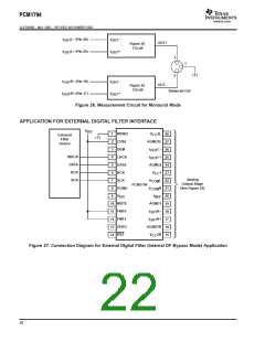
Application for Interfacing With an External Digital Filter
For some applications, it may be desirable to use a programmable digital signal processor as an external digital filter
to perform the interpolation function. The following pin settings enable the external digital filter application mode.
D
D
D
D
MONO (pin 1) = LOW
CHSL (Pin 2) = HIGH
FMT0 (Pin 11) = HIGH
FMT1 (pin 12) = HIGH
The pins used to provide the serial interface for the external digital filter are shown in the connection diagram of
Figure 27. The word clock (WDCK) must be operated at 8× or 4× the desired sampling frequency, f .
S
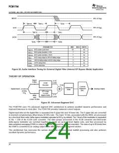
System Clock (SCK) and Interface Timing
The PCM1794 in an application using an external digital filter requires the synchronization of WDCK and the system
clock. The system clock is phase-free with respect to WDCK. Interface timing among WDCK, BCK, and DATA is
shown in Figure 29.
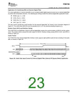
Audio Format
The PCM1794 in the external digital filter interface mode supports right-justified audio formats including 24-bit audio
data, as shown in Figure 28.
1/4 f or 1/8 f
S
S
WDCK
BCK
Audio Data Word = 24-Bit
23 24
1
2
3
4
5
6
7
8
9
10 11 12 13 14 15 16 17 18 19 20 21 22 23 24
LSB
DATA
MSB
Figure 28. Audio Data Input Format for External Digital Filter (Internal DF Bypass Mode) Application
23

 TI [ TEXAS INSTRUMENTS ]