PCM1794A
www.ti.com.cn
ZHCSEE9B –AUGUST 2004–REVISED DECEMBER 2015
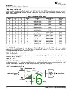
The PCM1794A device uses TI’s advanced segment DAC architecture to achieve excellent dynamic
performance and improved tolerance to clock jitter. The PCM1794A device provides balanced current outputs.
Digital input data using the digital filter is separated into 6 upper bits and 18 lower bits. The 6 upper bits are
converted to inverted complementary offset binary (ICOB) code. The lower 18 bits, associated with the MSB, are
processed by a five-level, third-order delta-sigma modulator operated at 64 fS by default. The 1 level of the
modulator is equivalent to the 1 LSB of the ICOB code converter. The data groups processed in the ICOB
converter and third-order delta-sigma modulator are summed together to create an up-to-66-level digital code,
and then processed by data-weighted averaging (DWA) to reduce the noise produced by element mismatch. The
data of up to 66 levels from the DWA is converted to an analog output in the differential-current segment section.
This architecture has overcome the various drawbacks of conventional multibit processing, and also achieves
excellent dynamic performance.
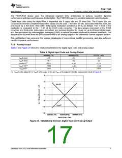
7.3.9 Analog Output
Table 4 and Figure 24 show the relationship between the digital input code and analog output.
Table 4. Digital Input Code and Analog Output
800000 (–FS)
–2.3
000000 (BPZ)
7FFFFF (+FS)
–10.1
IOUTN [mA]
IOUTP [mA]
VOUTN [V](1)
VOUTP [V](1)
VOUT [V](1)
–6.2
–6.2
–4.65
–4.65
0
–10.1
–2.3
–1.725
–7.575
–2.821
–7.575
–1.725
2.821
(1) VOUTN is the output of U1, VOUTP is the output of U2, and VOUT is the output of U3 in the measurement circuit of Figure 25.
0
−2
I N
OUT
−4
−6
−8
I P
OUT
−10
−12
800000(–FS)
000000(BPZ)
7FFFFF(+FS)
Input Code – Hex
Figure 24. Relationship Between Digital Input and Analog Output
Copyright © 2004–2015, Texas Instruments Incorporated
17

 TI [ TEXAS INSTRUMENTS ]