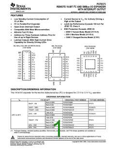
PCF8575
REMOTE 16-BIT I2C AND SMBus I/O EXPANDER
WITH INTERRUPT OUTPUT
www.ti.com
SCPS121C–JANUARY 2005–REVISED OCTOBER 2006
I2C Interface
The bidirectional I2C bus consists of the serial clock (SCL) and serial data (SDA) lines. Both lines must be
connected to a positive supply via a pullup resistor when connected to the output stages of a device. Data
transfer may be initiated only when the bus is not busy.
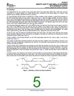
I2C communication with this device is initiated by a master sending a Start condition, a high-to-low transition on
the SDA input/output while the SCL input is high (see Figure 1). After the Start condition, the device address
byte is sent, most significant bit (MSB) first, including the data direction bit (R/W). This device does not respond
to the general call address. After receiving the valid address byte, this device responds with an ACK, a low on
the SDA input/output during the high of the ACK-related clock pulse. The address inputs (A2–A0) of the slave
device must not be changed between the Start and Stop conditions.
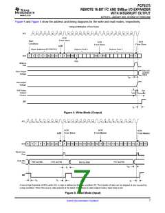
The data byte follows the address ACK. If the R/W bit is high, the data from this device are the values read from
the P port. If the R/W bit is low, the data are from the master, to be output to the P port. The data byte is
followed by an ACK sent from this device. If other data bytes are sent from the master, following the ACK, they
are ignored by this device. Data are output only if complete bytes are received and acknowledged. The output
data is valid at time (tpv) after the low-to-high transition of SCL, during the clock cycle for the ACK.
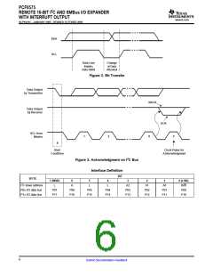
On the I2C bus, only one data bit is transferred during each clock pulse. The data on the SDA line must remain
stable during the high pulse of the clock period, as changes in the data line at this time are interpreted as control
commands (Start or Stop) (see Figure 2).
A Stop condition, a low-to-high transition on the SDA input/output while the SCL input is high, is sent by the
master (see Figure 1).
The number of data bytes transferred between the Start and Stop conditions from transmitter to receiver is not
limited. Each byte of eight bits is followed by one ACK bit. The transmitter must release the SDA line before the
receiver can send an ACK bit.
A slave receiver that is addressed must generate an ACK after the reception of each byte. Also, a master must
generate an ACK after the reception of each byte that has been clocked out of the slave transmitter. The device
that acknowledges has to pull down the SDA line during the ACK clock pulse so that the SDA line is stable low
during the high pulse of the ACK-related clock period (see Figure 3). Setup and hold times must be taken into
account.
A master receiver must signal an end of data to the transmitter by not generating an acknowledge (NACK) after
the last byte that has been clocked out of the slave. This is done by the master receiver by holding the SDA line
high. In this event, the transmitter must release the data line to enable the master to generate a Stop condition.
SDA
SCL
S
P
Start Condition
Stop Condition
Figure 1. Definition of Start and Stop Conditions
5
Submit Documentation Feedback

 TI [ TEXAS INSTRUMENTS ]