P82B715
I2C BUS EXTENDER
www.ti.com
SCPS145A–DECEMBER 2007–REVISED FEBRUARY 2008
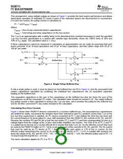
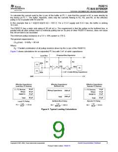
To calculate the current sunk by the Lx pin of the buffer at I2C 1, note that the current in R1 is sunk directly by
the device at I2C 1. The buffer, therefore, sinks only the currents flowing in R2, R3, and R4, so the effective
pullup is R2 in parallel with R3 and R4.
In this example that is 1 kΩ||10 kΩ||10 kΩ = 833 Ω. For a 5.5-V supply and 0.4-V low, the buffer is sinking
16.3 mA.
The P82B715 has a static sink rating of 30 mA at Lx. The requirement is that the pullup on the buffered bus, in
parallel with all other pullups that it is indirectly pulling low on Sx pins of other P82B715 devices, does not cause
this 30-mA limit to be exceeded.
The minimum pullup resistance in a 5-V ± 10% system is 170 Ω.
The general requirement is:
(VCC(max) – 0.4)/RP < 30 mA
Where:
Rp = Parallel combination of all pullup resistors driven by the Lx pin of the P82B715
Figure 5 shows calculations for an expanded I2C bus with 3 nF of cable capacitance.
Proposed Bus Expansion
Local Bus
VCC
5 V
R1
R2
R3
SDA
I2C
I2C
LDA
Sx
Lx
SDA
I2C
Lx
Sx
3 nF = Cable Wiring Capacitance
0 V
SDA
GND
Effective Capacitance
Local Bus I2C Devices
Effective Capacitance
Remote I2C Devices
Effective Capacitance
Buffered Line
2 × I2C Devices
1 × I2C Devices
20 pF
10 pF
Wiring Capacitance
Total
3000 pF
3000 pF
Strays
20 pF
10 pF
Strays
10 pF
10 pF
P82B715
P82B715
50 pF
Total
30 pF
Total
Local I2C Pullup
Buffered Bus Pullup
Remote I2C Pullup
1 µs
1 µs
1 µs
R1 =
= 20 kΩ
R2 =
= 330 Ω
R3 =
= 33 kΩ
50 pF
3000 pF
30 pF
Figure 5. Typical Loading Calculations
Copyright © 2007–2008, Texas Instruments Incorporated
Submit Documentation Feedback
9
Product Folder Link(s): P82B715

 TI [ TEXAS INSTRUMENTS ]