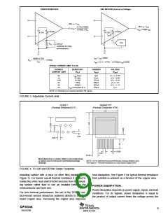
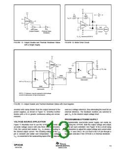
RESISTOR METHOD
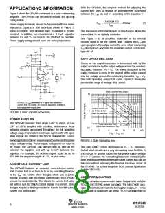
DAC METHOD (Current or Voltage)
Max IO = ILIM
Max IO = ILIM
(4.75) (15000)
±ILIM
=
±ILIM =15000 ISET
13750Ω + RCL
13750Ω
13750Ω
4.75V
4.75V
ISET
3
3
D/A
RCL
0.01µF
(optional, for noisy
environments)
4
4
V–
V–
ISET = ILIM /15000
SET = (V–) + 4.75V – (13750Ω) (ILIM)/15000
15000 (4.75V)
ILIM
RCL
=
– 13750Ω
V
OPA547 CURRENT LIMIT: 0 to 5A
DESIRED
CURRENT LIMIT
RESISTOR(1)
(RCL
CURRENT
(ISET
VOLTAGE
(VSET
)
)
)
0A
1A
2.5A
3A
4A
5A
I
LIM Open
57.6kΩ
14.7kΩ
10kΩ
0µA
67µA
167µA
200µA
267µA
333µA
(V–) + 4.75V
(V–) + 3.8V
(V–) + 2.5V
(V–) + 2V
(V–) + 1.1V
(V–)
4.02kΩ
ILIM Connected to V–
NOTE: (1) Resistors are nearest standard 1% values.
FIGURE 3. Adjustable Current Limit.
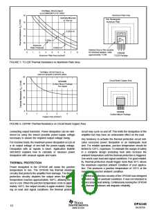
(1)
DDPAK-7
(Package Designator KTW)
TO220-7
(Package Designator KVT)
0.51
0.04
0.05
0.035
0.05
0.105
Mean dimensions in inches. Refer to end of data sheet
or www.ti.com for tolerances and detailed package
drawings.
NOTE: (1) For improved thermal performance increase footprint area.
See Figure 6, “Thermal Resistance vs Circuit Board Copper Area”.
FIGURE 4. TO-220 and DDPAK Solder Footprints.
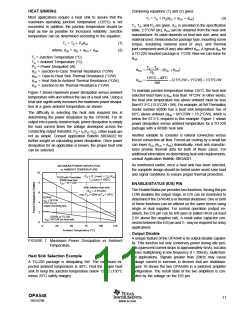
mounting surface with a mica (or other film) insulator (see
Figure 5). For lowest overall thermal resistance it is best to
isolate the entire heat sink/OPA548 structure from the mount-
ing surface rather than to use an insulator between the
semiconductor and heat sink.
heat dissipation. See Figure 6 for typical thermal resistance
from junction-to-ambient as a function of the copper area.
POWER DISSIPATION
Power dissipation depends on power supply, signal, and load
conditions. For dc signals, power dissipation is equal to
the product of output current times the voltage across the
For best thermal performance, the tab of the DDPAK sur-
face-mount version should be soldered directly to a circuit
board copper area. Increasing the copper area improves
OPA548
SBOS070B
9
www.ti.com

 TI [ TEXAS INSTRUMENTS ]