HEAT SINKING
Combining equations (1) and (2) gives:
TJ = TA + PD(θJC + θCH + θHA
Most applications require a heat sink to assure that the
maximum operating junction temperature (125°C) is not
exceeded. In addition, the junction temperature should be
kept as low as possible for increased reliability. Junction
temperature can be determined according to the equation:
)
(3)
TJ, TA, and PD are given. θJC is provided in the specification
table, 2.5°C/W (dc). θCH can be obtained from the heat sink
manufacturer. Its value depends on heat sink size, area, and
material used. Semiconductor package type, mounting screw
torque, insulating material used (if any), and thermal
joint compound used (if any) also affect θCH. A typical θCH for
a TO-220 mounted package is 1°C/W. Now we can solve for
TJ = TA + PDθJA
(1)
(2)
where, θJA = θJC + θCH + θHA
TJ = Junction Temperature (°C)
TA = Ambient Temperature (°C)
θHA
:
PD = Power Dissipated (W)
θJC = Junction-to-Case Thermal Resistance (°C/W)
θCH = Case-to-Heat Sink Thermal Resistance (°C/W)
TJ – TA
θHA
θHA
=
=
– θ + θCH
JC
(
)
PD
125°C – 40°C
– 2.5°C/W + 1°C/W = 13.5°C/W
(
)
θHA
= Heat Sink-to-Ambient Thermal Resistance (°C/W)
5W
θJA = Junction-to-Air Thermal Resistance (°C/W)
To maintain junction temperature below 125°C, the heat sink
selected must have a θHA less than 14°C/W. In other words,
the heat sink temperature rise above ambient must be less
than 67.5°C (13.5°C/W • 5W). For example, at 5W Thermalloy
model number 6030B has a heat sink temperature rise of
66°C above ambient (θHA = 66°C/5W = 13.2°C/W), which is
below the 67.5°C required in this example. Figure 7 shows
power dissipation versus ambient temperature for a TO-220
package with a 6030B heat sink.
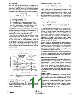
Figure 7 shows maximum power dissipation versus ambient
temperature with and without the use of a heat sink. Using a
heat sink significantly increases the maximum power dissipa-
tion at a given ambient temperature as shown.
The difficulty in selecting the heat sink required lies in
determining the power dissipated by the OPA548. For dc
output into a purely resistive load, power dissipation is simply
the load current times the voltage developed across the
conducting output transistor, PD = IL(VS–VO). Other loads are
not as simple. Consult Application Bulletin SBOA022 for
further insight on calculating power dissipation. Once power
dissipation for an application is known, the proper heat sink
can be selected.
Another variable to consider is natural convection versus
forced convection air flow. Forced-air cooling by a small fan
can lower θCA (θCH + θHA) dramatically. Heat sink manufac-
tures provide thermal data for both of these cases. For
additional information on determining heat sink requirements,
consult Application Bulletin SBOA021.
As mentioned earlier, once a heat sink has been selected,
the complete design should be tested under worst-case load
and signal conditions to ensure proper thermal protection.
MAXIMUM POWER DISSIPATION
vs AMBIENT TEMPERATURE
10
PD = (TJ (max) – TA) /θJA
TO220 with Thermalloy
6030B Heat Sink
TJ (max) = 150°C
8
6
4
2
0
θ
= 16.7°C/W
JA
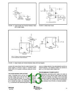
ENABLE/STATUS (E/S) PIN
With infinite heat sink
The Enable/Status pin provides two functions: forcing this pin
LOW disables the output stage, or E/S can be monitored to
determine if the OPA548 is in thermal shutdown. One or both
of these functions can be utilized on the same device using
single or dual supplies. For normal operation (output en-
abled), the E/S pin can be left open or pulled HIGH (at least
2.4V above the negative rail). A small value capacitor con-
nected between the E/S pin and V– may be required for noisy
applications.
(
θJA = 2.5°C/W),
max PD = 50W at TA = 25°C.
DDPAK
= 26°C/W
(3 in one oz
θ
JA
2
copper mounting pad)
DDPAK or TO-220
= 65°C/W (no heat sink)
θ
JA
0
25
50
75
100
125
Ambient Temperature (°C)
Output Disable
A unique feature of the OPA548 is its output disable capabil-
ity. This function not only conserves power during idle peri-
ods (quiescent current drops to approximately 6mA), but also
allows multiplexing in low frequency (f < 20kHz), multichan-
nel applications. Signals greater than 20kHz may cause
leakage current to increase in devices that are shutdown.
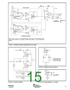
Figure 18 shows the two OPA548s in a switched amplifier
configuration. The on/off state of the two amplifiers is con-
trolled by the voltage on the E/S pin.
FIGURE 7. Maximum Power Dissipation vs Ambient
Temperature.
Heat Sink Selection Example
A TO-220 package is dissipating 5W. The maximum ex-
pected ambient temperature is 40°C. Find the proper heat
sink to keep the junction temperature below 125°C (150°C
minus 25°C safety margin).
OPA548
SBOS070B
11
www.ti.com

 TI [ TEXAS INSTRUMENTS ]