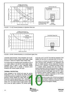
V+
V+
R2
R1
R1
5kΩ
R2
20kΩ
G = –
= –4
VIN
OPA548
D1
E/S
OPA548
V–
10Ω
(Carbon)
D2
Motor
Open Drain
HCT
(Output Disable)
(Thermal Status
Shutdown)
0.01µF
V–
D1, D2 : Motorola MUR410.
FIGURE 12. Output Disable and Thermal Shutdown Status
with a Single Supply.
FIGURE 14. Motor Drive Circuit.
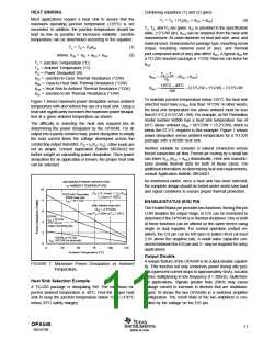
V+
5V
5V
1
6
5
4
OPA548
E/S
7.5kΩ
1W
TTL Out
1
6
2
(1)
Zetex
ZVN3310
4N38
5
4
Optocoupler
HCT or TTL In
2
4N38
Optocoupler
V–
NOTE: (1) Optional—may be required to limit leakage
current of optocoupler at high temperatures.
FIGURE 13. Output Disable and Thermal Shutdown Status with Dual Supplies.
avoided with clamp diodes from the output terminal to the
power supplies, as shown in Figure 14. Schottky rectifier
diodes with a 5A or greater continuous rating are recom-
mended.
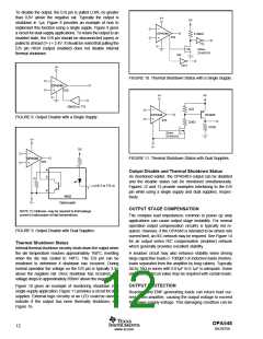
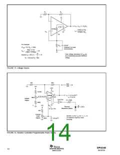
used as a voltage reference, thus eliminating the need for an
external reference. The feedback resistors are selected to
gain VCL to the desired output voltage level.
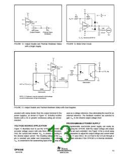
PROGRAMMABLE POWER SUPPLY
VOLTAGE SOURCE APPLICATION
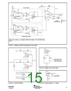
A programmable source/sink power supply can easily be
built using the OPA548. Both the output voltage and output
current are user-controlled. See Figure 16 for a circuit using
potentiometers to adjust the output voltage and current while
Figure 17 uses DACs. An LED tied to the E/S pin through a
logic gate indicates if the OPA548 is in thermal shutdown.
Figure 15 illustrates how to use the OPA548 to provide an
accurate voltage source with only three external resistors.
First, the current limit resistor, RCL, is chosen according to
the desired output current. The resulting voltage at the ILIM
pin is constant and stable over temperature. This voltage,
VCL, is connected to the noninverting input of the op amp and
OPA548
SBOS070B
13
www.ti.com

 TI [ TEXAS INSTRUMENTS ]