OMAP-L137 Low-Power Applications Processor
SPRS563A–SEPTEMBER 2008–REVISED OCTOBER 2008
www.ti.com
Table 6-73. eHRPWM Switching Characteristics (continued)
PARAMETER
TEST CONDITIONS
MIN
MAX
UNIT
td(TZ-PWM)HZ
Delay time, trip input active to PWM Hi-Z
20
ns
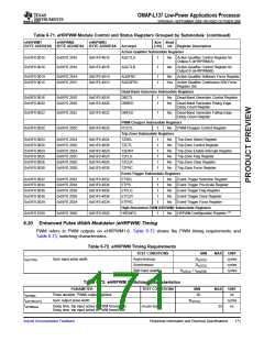
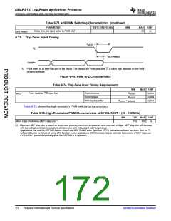
6.21 Trip-Zone Input Timing
t
w(TZ)
TZ
t
d(TZ-PWM)HZ
(A)
PWM
A. PWM refers to all the PWM pins in the device. The state of the PWM pins after TZ is taken high depends on the PWM
recovery software.
Figure 6-45. PWM Hi-Z Characteristics
Table 6-74. Trip-Zone input Timing Requirements
MIN
1tc(SCO)
MAX UNIT
cycles
tw(TZ)
Pulse duration, TZx input low
Asynchronous
Synchronous
2tc(SCO)
cycles
With input qualifier
1tc(SCO) + tw(IQSW)
cycles
Table 6-75 shows the high-resolution PWM switching characteristics.
Table 6-75. High Resolution PWM Characteristics at SYSCLKOUT = (60 - 100 MHz)
MIN
TYP
MAX UNIT
Micro Edge Positioning (MEP) step size(1)
150
310
ps
(1) Maximum MEP step size is based on worst-case process, maximum temperature and maximum voltage. MEP step size will increase
with low voltage and high temperature and decrease with voltage and cold temperature.
Applications that use the HRPWM feature should use MEP Scale Factor Optimizer (SFO) estimation software functions. See the TI
software libraries for details of using SFO function in end applications. SFO functions help to estimate the number of MEP steps per
SYSCLKOUT period dynamically while the HRPWM is in operation.
172
Peripheral Information and Electrical Specifications
Submit Documentation Feedback

 TI [ TEXAS INSTRUMENTS ]