OMAP-L137 Low-Power Applications Processor
www.ti.com
SPRS563A–SEPTEMBER 2008–REVISED OCTOBER 2008
6.11.1 Interfacing to SDRAM
The EMIFB supports a glueless interface to SDRAM devices with the following characteristics:
•
•
•
Pre-charge bit is A[10]
The number of column address bits is 8, 9, 10 or 11
The number of row address bits is 13 (in case of mobile SDR, number of row address bits can be 9,
10, 11, 12, or 13)
•
The number of internal banks is 1, 2 or 4
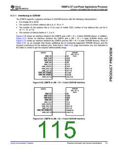
Figure 6-20 shows an interface between the EMIFB and a 2M × 16 × 4 bank SDRAM device. In addition,
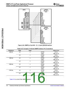
Figure 6-21 shows an interface between the EMIFB and a 2M × 32 × 4 bank SDRAM device and
Figure 6-22 shows an interface between the EMIFB and two 4M × 16 × 4 bank SDRAM devices. Refer to
Table 6-22, as an example that shows additional list of commonly-supported SDRAM devices and the
required connections for the address pins. Note that in Table 6-22, page size/column size (not indicated in
the table) is varied to get the required addressability range.
SDRAM
2M x 16 x 4
Bank
EMIFB
EMB_CS
CE
EMB_CAS
EMB_RAS
CAS
RAS
WE
EMB_WE
EMB_CLK
CLK
CKE
EMB_SDCKE
EMB_BA[1:0]
EMB_A[11:0]
EMB_WE_DQM[0]
EMB_WE_DQM[1]
EMB_D[15:0]
BA[1:0]
A[11:0]
LDQM
UDQM
DQ[15:0]
Figure 6-20. EMIFB to 2M × 16 × 4 bank SDRAM Interface
SDRAM
2M x 32 x 4
Bank
EMIFB
EMB_CS
CE
EMB_CAS
EMB_RAS
CAS
RAS
WE
EMB_WE
EMB_CLK
CLK
CKE
EMB_SDCKE
EMB_BA[1:0]
EMB_A[11:0]
EMB_WE_DQM[3:0]
EMB_D[31:0]
BA[1:0]
A[11:0]
DQM[3:0]
DQ[31:0]
Figure 6-21. EMIFB to 2M × 32 × 4 bank SDRAM Interface
Submit Documentation Feedback
Peripheral Information and Electrical Specifications
115

 TI [ TEXAS INSTRUMENTS ]