OMAP-L137 Low-Power Applications Processor
SPRS563A–SEPTEMBER 2008–REVISED OCTOBER 2008
www.ti.com
6.11 EMIFB Peripheral Registers Description(s)
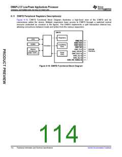
Figure 6-19, EMIFB Functional Block Diagram illustrates a high-level view of the EMIFB and its
connections within the device. Multiple requesters have access to EMIFB through a switched central
resource (indicated as crossbar in the figure). The EMIFB implements a split transaction internal bus,
allowing concurrence between reads and writes from the various requesters.
EMIFB
Registers
CPU
EMB_CS
EMB_CAS
EDMA
Cmd/Write
FIFO
EMB_RAS
EMB_WE
Crossbar
Master
Peripherals
(USB, UHPI...)
EMB_CLK
SDRAM
Interface
EMB_SDCKE
EMB_BA[1:0]
EMB_A[x:0]
Read
FIFO
EMB_D[x:0]
EMB_WE_DQM[x:0]
Figure 6-19. EMIFB Functional Block Diagram
114
Peripheral Information and Electrical Specifications
Submit Documentation Feedback

 TI [ TEXAS INSTRUMENTS ]