MSP430F530x, MSP430F5310
SLAS677B –SEPTEMBER 2010–REVISED MARCH 2011
www.ti.com
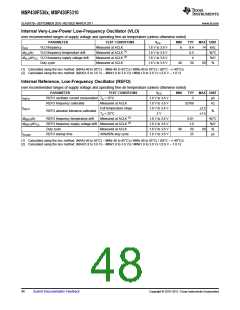
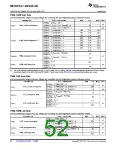
Internal Very-Low-Power Low-Frequency Oscillator (VLO)
over recommended ranges of supply voltage and operating free-air temperature (unless otherwise noted)
PARAMETER
VLO frequency
VLO frequency temperature drift
TEST CONDITIONS
VCC
MIN
TYP
9.4
0.5
4
MAX UNIT
14 kHz
%/°C
fVLO
Measured at ACLK
1.8 V to 3.6 V
1.8 V to 3.6 V
1.8 V to 3.6 V
1.8 V to 3.6 V
6
(1)
(2)
dfVLO/dT
Measured at ACLK
Measured at ACLK
Measured at ACLK
dfVLO/dVCC VLO frequency supply voltage drift
Duty cycle
%/V
40
50
60
%
(1) Calculated using the box method: (MAX(-40 to 85°C) – MIN(-40 to 85°C)) / MIN(-40 to 85°C) / (85°C – (–40°C))
(2) Calculated using the box method: (MAX(1.8 to 3.6 V) – MIN(1.8 to 3.6 V)) / MIN(1.8 to 3.6 V) / (3.6 V – 1.8 V)
Internal Reference, Low-Frequency Oscillator (REFO)
over recommended ranges of supply voltage and operating free-air temperature (unless otherwise noted)
PARAMETER
TEST CONDITIONS
VCC
MIN
TYP
3
MAX UNIT
IREFO
REFO oscillator current consumption TA = 25°C
1.8 V to 3.6 V
1.8 V to 3.6 V
1.8 V to 3.6 V
3 V
µA
REFO frequency calibrated
Measured at ACLK
32768
Hz
fREFO
Full temperature range
±3.5
%
REFO absolute tolerance calibrated
REFO frequency temperature drift
TA = 25°C
±1.5
(1)
dfREFO/dT
Measured at ACLK
1.8 V to 3.6 V
1.8 V to 3.6 V
1.8 V to 3.6 V
1.8 V to 3.6 V
0.01
1.0
50
%/°C
(2)
dfREFO/dVCC
REFO frequency supply voltage drift Measured at ACLK
%/V
Duty cycle
Measured at ACLK
40%/60% duty cycle
40
60
%
tSTART
REFO startup time
25
µs
(1) Calculated using the box method: (MAX(-40 to 85°C) – MIN(-40 to 85°C)) / MIN(-40 to 85°C) / (85°C – (–40°C))
(2) Calculated using the box method: (MAX(1.8 to 3.6 V) – MIN(1.8 to 3.6 V)) / MIN(1.8 to 3.6 V) / (3.6 V – 1.8 V)
48
Submit Documentation Feedback
Copyright © 2010–2011, Texas Instruments Incorporated

 TI [ TEXAS INSTRUMENTS ]