MSP430G2x53
MSP430G2x13
www.ti.com
SLAS735A –APRIL 2011–REVISED MAY 2011
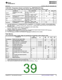
10-Bit ADC, Temperature Sensor and Built-In VMID (MSP430G2x53 Only)
over recommended ranges of supply voltage and operating free-air temperature (unless otherwise noted)
PARAMETER
TEST CONDITIONS
VCC
3 V
3 V
3 V
3 V
3 V
MIN
TYP
60
MAX UNIT
Temperature sensor supply
current(1)
REFON = 0, INCHx = 0Ah,
TA = 25°C
ISENSOR
TCSENSOR
tSensor(sample)
IVMID
µA
mV/°C
µs
(2)
ADC10ON = 1, INCHx = 0Ah
ADC10ON = 1, INCHx = 0Ah,
Error of conversion result ≤ 1 LSB
3.55
Sample time required if channel
30
(3)
10 is selected
(4)
Current into divider at channel 11 ADC10ON = 1, INCHx = 0Bh
µA
ADC10ON = 1, INCHx = 0Bh,
VCC divider at channel 11
VMID
1.5
V
V
MID ≉ 0.5 × VCC
Sample time required if channel
11 is selected
ADC10ON = 1, INCHx = 0Bh,
Error of conversion result ≤ 1 LSB
tVMID(sample)
3 V
1220
ns
(5)
(1) The sensor current ISENSOR is consumed if (ADC10ON = 1 and REFON = 1) or (ADC10ON = 1 and INCH = 0Ah and sample signal is
high). When REFON = 1, ISENSOR is included in IREF+. When REFON = 0, ISENSOR applies during conversion of the temperature sensor
input (INCH = 0Ah).
(2) The following formula can be used to calculate the temperature sensor output voltage:
VSensor,typ = TCSensor (273 + T [°C] ) + VOffset,sensor [mV] or
VSensor,typ = TCSensor T [°C] + VSensor(TA = 0°C) [mV]
(3) The typical equivalent impedance of the sensor is 51 kΩ. The sample time required includes the sensor-on time tSENSOR(on)
(4) No additional current is needed. The VMID is used during sampling.
.
(5) The on-time tVMID(on) is included in the sampling time tVMID(sample); no additional on time is needed.
Flash Memory
over recommended ranges of supply voltage and operating free-air temperature (unless otherwise noted)
PARAMETER
TEST
CONDITIONS
VCC
MIN
TYP
MAX
UNIT
VCC(PGM/ERASE) Program and erase supply voltage
2.2
3.6
476
5
V
kHz
mA
fFTG
Flash timing generator frequency
Supply current from VCC during program
Supply current from VCC during erase
Cumulative program time(1)
257
IPGM
2.2 V/3.6 V
2.2 V/3.6 V
2.2 V/3.6 V
2.2 V/3.6 V
1
1
IERASE
tCPT
7
mA
10
ms
tCMErase
Cumulative mass erase time
20
104
100
ms
Program/erase endurance
105
cycles
years
tFTG
tFTG
tRetention
tWord
Data retention duration
TJ = 25°C
(2)
Word or byte program time
30
25
(2)
(2)
tBlock, 0
Block program time for first byte or word
Block program time for each additional byte or
word
tBlock, 1-63
18
tFTG
(2)
(2)
(2)
tBlock, End
tMass Erase
tSeg Erase
Block program end-sequence wait time
Mass erase time
6
10593
4819
tFTG
tFTG
tFTG
Segment erase time
(1) The cumulative program time must not be exceeded when writing to a 64-byte flash block. This parameter applies to all programming
methods: individual word/byte write and block write modes.
(2) These values are hardwired into the Flash Controller's state machine (tFTG = 1/fFTG).
Copyright © 2011, Texas Instruments Incorporated
Submit Documentation Feedback
39

 TI [ TEXAS INSTRUMENTS ]