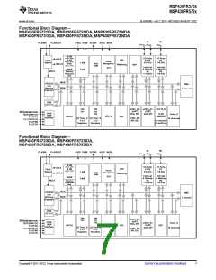
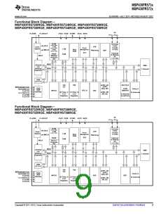
MSP430FR573x
MSP430FR572x
www.ti.com
SLAS639D –JULY 2011–REVISED AUGUST 2012
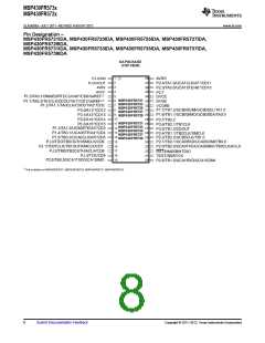
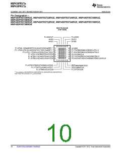
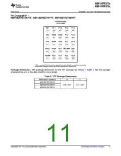
Pin Designation –
MSP430FR5730IYFF, MSP430FR5736IYFF, MSP430FR5738IYFF
YFF PACKAGE
(TOP VIEW)
NC1
P1.1
P1.3
P1.2
P1.5
A1
A2
A3
A4
A5
PJ.5
AVCC AVSS
P1.4
PJ.1
B1
B2
B3
B4
B5
PJ.4
AVSS
PJ.2
PJ.3
PJ.0
C1
C2
C4
C5
C3
DVCC DVSS
D1 D2
P2.1 RST/NMI TEST
D3
D4
D5
VCORE P1.6
E1 E2
P1.7
P2.2
P2.0
E3
E4
E5
1
NC (no connect). This ball must be attached but remain floating (no electrical connection).
P1.0 must be initialized properly to avoid the floating input of the device.
Package Dimensions: The package dimensions for the YFF package are shown in Table 3. See the package
drawing at the end of this data sheet for more details.
Table 3. YFF Package Dimensions
PACKAGED DEVICES
MSP430FR5738IYFF
MSP430FR5736IYFF
MSP430FR5730IYFF
D
E
2.04 ± 0.03
2.24 ± 0.03
Copyright © 2011–2012, Texas Instruments Incorporated
Submit Documentation Feedback
11

 TI [ TEXAS INSTRUMENTS ]