LMH0324
www.ti.com.cn
ZHCSIC8B –APRIL 2016–REVISED JUNE 2018
7.4.1.1 SMBus Read and Write Transactions
SMBus is a two-wire serial interface through which various system component chips can communicate with the
master. Slave devices are identified by having a unique device address. The two-wire serial interface consists of
SCL and SDA signals. SCL is a clock output from the master to all of the slave devices on the bus. SDA is a
bidirectional data signal between the master and slave devices. The LMH0324 SMBus SCL and SDA signals are
open drain and require external pull-up resistors.
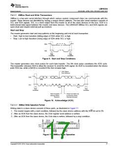
Start and Stop:
The master generates start and stop patterns at the beginning and end of each transaction.
•
•
Start: High to low transition (falling edge) of SDA while SCL is high.
Stop: Low to high transition (rising edge) of SDA while SCL is high.
SDA
SCL
S
P
Start
Stop
Condition
Condition
Figure 9. Start and Stop Conditions
The master generates nine clock pulses for each byte transfer. The 9th clock pulse constitutes the ACK cycle.
The transmitter releases SDA to allow the receiver to send the ACK signal. An ACK is recorded when the device
pulls SDA low, while a NACK is recorded if the line remains high.
ACK Signal
from Receiver
SDA
MSB
SCL
1
2
3 - 6
7
8
9
1
2
3 - 8
9
S
P
ACK
ACK
Start
Stop
Condition
Condition
Byte Complete
Interrupt Within
Receiver
Clock Line Held Low
by Receiver While
Interrupt Serviced
Figure 10. Acknowledge (ACK)
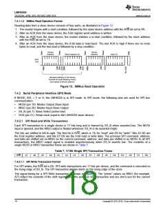
7.4.1.1.1 SMBus Write Operation Format
Writing data to a slave device consists of three parts, as illustrated in Figure 11:
1. The master begins with a start condition, followed by the slave device address with the R/W bit set to 0'b.
2. After an ACK from the slave device, the 8-bit register word address is written.
3. After an ACK from the slave device, the 8-bit data is written, followed by a stop condition.
Device
Address
Word Address
Data
SDA
Line
Figure 11. SMBus Write Operation
Copyright © 2016–2018, Texas Instruments Incorporated
17

 TI [ TEXAS INSTRUMENTS ]