LMH0324
ZHCSIC8B –APRIL 2016–REVISED JUNE 2018
www.ti.com.cn
7.4 Device Functional Modes
The LMH0324 operates in one of two modes: System Management Bus (SMBus) or Serial Peripheral Interface
(SPI) mode. In order to determine the mode of operation, the proper setting must be applied to the MODE_SEL
pin at power-up, as detailed in Table 5.
Table 5. MODE_SEL Pin Settings
LEVEL
DEFINITION
Forced Power Save Mode, only SPI is enabled (all other circuitry powered down)
Select SPI Interface for register access
H
F
R
L
Reserved for factory testing – do not use
Select SMBus Interface for register access
NOTE
Changing logic states between LEVEL-L and LEVEL-H after power up is not allowed.
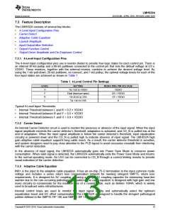
7.4.1 System Management Bus (SMBus) Mode
If MODE_SEL = L, the LMH0324 is in SMBus mode. In SMBus mode, Pins 10 and 21 are configured as SDA
and SCL. Pins 7 and 20 act as 4-level address straps for ADDR0 and ADDR1 at power up to determine the 7-bit
slave address of the LMH0324, as shown in Table 6.
Table 6. SMBus Device Slave Addresses(1)
ADDR0
ADDR1
7-BIT SLAVE
8-BIT WRITE
(LEVEL)
(LEVEL)
ADDRESS [HEX]
COMMAND [HEX]
L
L
L
R
F
H
L
1D
1E
1F
20
21
22
23
24
25
26
27
28
29
2A
2B
2C
3A
3C
3E
40
42
44
46
48
4A
4C
4E
50
52
54
56
58
L
L
R
R
R
R
F
F
F
F
H
H
H
H
R
F
H
L
R
F
H
L
R
F
H
(1) The 8-bit write command consists of the 7-bit slave address (Bits 7:1) with 0 appended to the LSB to
indicate an SMBus write. For example, if the 7-bit slave address is 0x1D (001 1101'b), the 8-bit write
command is 0x3A (0011 1010'b).
16
Copyright © 2016–2018, Texas Instruments Incorporated

 TI [ TEXAS INSTRUMENTS ]