LM3886
SNAS091C –MAY 1999–REVISED MARCH 2013
www.ti.com
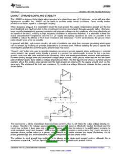
The single-point ground concept should be applied rigorously to all components and all circuits when possible.
Violations of single-point grounding are most common among printed circuit board designs, since the circuit is
surrounded by large ground areas which invite the temptation to run a device to the closest ground spot. As a
final rule, make all ground returns low resistance and low inductance by using large wire and wide traces.
Occasionally, current in the output leads (which function as antennas) can be coupled through the air to the
amplifier input, resulting in high-frequency oscillation. This normally happens when the source impedance is high
or the input leads are long. The problem can be eliminated by placing a small capacitor, CC, (on the order of 50
pF to 500 pF) across the LM3886 input terminals. Refer to External Components Description relating to
component interaction with Cf.
REACTIVE LOADING
It is hard for most power amplifiers to drive highly capacitive loads very effectively and normally results in
oscillations or ringing on the square wave response. If the output of the LM3886 is connected directly to a
capacitor with no series resistance, the square wave response will exhibit ringing if the capacitance is greater
than about 0.2 μF. If highly capacitive loads are expected due to long speaker cables, a method commonly
employed to protect amplifiers from low impedances at high frequencies is to couple to the load through a 10Ω
resistor in parallel with a 0.7 μH inductor. The inductor-resistor combination as shown in Typical Application
isolates the feedback amplifier from the load by providing high output impedance at high frequencies thus
allowing the 10Ω resistor to decouple the capacitive load and reduce the Q of the series resonant circuit. The LR
combination also provides low output impedance at low frequencies thus shorting out the 10Ω resistor and
allowing the amplifier to drive the series RC load (large capacitive load due to long speaker cables) directly.
GENERALIZED AUDIO POWER AMPLIFIER DESIGN
The system designer usually knows some of the following parameters when starting an audio amplifier design:
Desired Power Output
Input Impedance
Input Level
Load Impedance
Bandwidth
Maximum Supply Voltage
The power output and load impedance determine the power supply requirements, however, depending upon the
application some system designers may be limited to certain maximum supply voltages. If the designer does
have a power supply limitation, he should choose a practical load impedance which would allow the amplifier to
provide the desired output power, keeping in mind the current limiting capabilities of the device. In any case, the
output signal swing and current are found from (where PO is the average output power):
(7)
(8)
To determine the maximum supply voltage the following parameters must be considered. Add the dropout
voltage (4V for LM3886) to the peak output swing, Vopeak, to get the supply rail value (i.e. ± (Vopeak + Vod) at a
current of Iopeak). The regulation of the supply determines the unloaded voltage, usually about 15% higher.
Supply voltage will also rise 10% during high line conditions. Therefore, the maximum supply voltage is obtained
from the following equation:
Max. supplies ≊ ± (Vopeak + Vod)(1 + regulation)(1.1)
(9)
The input sensitivity and the output power specs determine the minimum required gain as depicted below:
(10)
Normally the gain is set between 20 and 200; for a 40W, 8Ω audio amplifier this results in a sensitivity of 894 mV
and 89 mV, respectively. Although higher gain amplifiers provide greater output power and dynamic headroom
capabilities, there are certain shortcomings that go along with the so called “gain.” The input referred noise floor
is increased and hence the SNR is worse. With the increase in gain, there is also a reduction of the power
bandwidth which results in a decrease in feedback thus not allowing the amplifier to respond quickly enough to
nonlinearities. This decreased ability to respond to nonlinearities increases the THD + N specification.
22
Submit Documentation Feedback
Copyright © 1999–2013, Texas Instruments Incorporated
Product Folder Links: LM3886

 TI [ TEXAS INSTRUMENTS ]