LM3886
www.ti.com
SNAS091C –MAY 1999–REVISED MARCH 2013
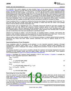
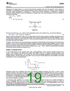
Referring to the figure below, it is seen that the thermal resistance from the die (junction) to the outside air
(ambient) is a combination of three thermal resistances, two of which are known, θJC and θCS. Since convection
heat flow (power dissipation) is analogous to current flow, thermal resistance is analogous to electrical
resistance, and temperature drops are analogous to voltage drops, the power dissipation out of the LM3886 is
equal to the following:
PDMAX = (TJmax − TAmb)/θJA
where
•
θJA = θJC + θCS + θSA
(5)
Figure 50.
But since we know PDMAX, θJC, and θSC for the application and we are looking for θSA, we have the following:
θSA = [(TJmax − TAmb) − PDMAX (θJC + θCS)]/PDMAX
(6)
Again it must be noted that the value of θSA is dependent upon the system designer's amplifier application and its
corresponding parameters as described previously. If the ambient temperature that the audio amplifier is to be
working under is higher than the normal 25°C, then the thermal resistance for the heat sink, given all other things
are equal, will need to be smaller.
Equation 2 and Equation 6 are the only equations needed in the determination of the maximum heat sink thermal
resistance. This is of course given that the system designer knows the required supply voltages to drive his rated
load at a particular power output level and the parameters provided by the semiconductor manufacturer. These
parameters are the junction to case thermal resistance, θJC, TJmax = 150°C, and the recommended Thermalloy
Thermacote thermal compound resistance, θCS
.
SIGNAL-TO-NOISE RATIO
In the measurement of the signal-to-noise ratio, misinterpretations of the numbers actually measured are
common. One amplifier may sound much quieter than another, but due to improper testing techniques, they
appear equal in measurements. This is often the case when comparing integrated circuit designs to discrete
amplifier designs. Discrete transistor amps often “run out of gain” at high frequencies and therefore have small
bandwidths to noise as indicated below.
Integrated circuits have additional open loop gain allowing additional feedback loop gain in order to lower
harmonic distortion and improve frequency response. It is this additional bandwidth that can lead to erroneous
signal-to-noise measurements if not considered during the measurement process. In the typical example above,
the difference in bandwidth appears small on a log scale but the factor of 10 in bandwidth, (200 kHz to 2 MHz)
can result in a 10 dB theoretical difference in the signal-to-noise ratio (white noise is proportional to the square
root of the bandwidth in a system).
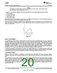
In comparing audio amplifiers it is necessary to measure the magnitude of noise in the audible bandwidth by
using a “weighting” filter (see Note below). A “weighting” filter alters the frequency response in order to
compensate for the average human ear's sensitivity to the frequency spectra. The weighting filters at the same
time provide the bandwidth limiting as discussed in the previous paragraph.
Copyright © 1999–2013, Texas Instruments Incorporated
Submit Documentation Feedback
19
Product Folder Links: LM3886

 TI [ TEXAS INSTRUMENTS ]