LM3886
www.ti.com
SNAS091C –MAY 1999–REVISED MARCH 2013
LAYOUT, GROUND LOOPS AND STABILITY
The LM3886 is designed to be stable when operated at a closed-loop gain of 10 or greater, but as with any other
high-current amplifier, the LM3886 can be made to oscillate under certain conditions. These usually involve
printed circuit board layout or output/input coupling.
When designing a layout, it is important to return the load ground, the output compensation ground, and the low
level (feedback and input) grounds to the circuit board common ground point through separate paths. Otherwise,
large currents flowing along a ground conductor will generate voltages on the conductor which can effectively act
as signals at the input, resulting in high frequency oscillation or excessive distortion. It is advisable to keep the
output compensation components and the 0.1 μF supply decoupling capacitors as close as possible to the
LM3886 to reduce the effects of PCB trace resistance and inductance. For the same reason, the ground return
paths should be as short as possible.
In general, with fast, high-current circuitry, all sorts of problems can arise from improper grounding which again
can be avoided by returning all grounds separately to a common point. Without isolating the ground signals and
returning the grounds to a common point, ground loops may occur.
“Ground Loop” is the term used to describe situations occurring in ground systems where a difference in potential
exists between two ground points. Ideally a ground is a ground, but unfortunately, in order for this to be true,
ground conductors with zero resistance are necessary. Since real world ground leads possess finite resistance,
currents running through them will cause finite voltage drops to exist. If two ground return lines tie into the same
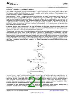
path at different points there will be a voltage drop between them. The first figure below shows a common ground
example where the positive input ground and the load ground are returned to the supply ground point via the
same wire. The addition of the finite wire resistance, R2, results in a voltage difference between the two points as
shown below.
The load current IL will be much larger than input bias current II, thus V1 will follow the output voltage directly, i.e.
in phase. Therefore the voltage appearing at the non-inverting input is effectively positive feedback and the
circuit may oscillate. If there were only one device to worry about then the values of R1 and R2 would probably be
small enough to be ignored; however, several devices normally comprise a total system. Any ground return of a
separate device, whose output is in phase, can feedback in a similar manner and cause instabilities. Out of
phase ground loops also are troublesome, causing unexpected gain and phase errors.
The solution to most ground loop problems is to always use a single-point ground system, although this is
sometimes impractical. The third figure below is an example of a single-point ground system.
Copyright © 1999–2013, Texas Instruments Incorporated
Submit Documentation Feedback
21
Product Folder Links: LM3886

 TI [ TEXAS INSTRUMENTS ]