LM3410, LM3410Q
SNVS541G –OCTOBER 2007–REVISED MAY 2013
www.ti.com
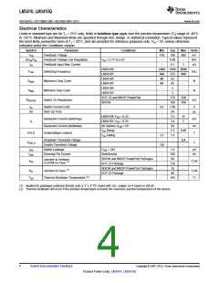
Electrical Characteristics
Limits in standard type are for TJ = 25°C only; limits in boldface type apply over the junction temperature (TJ) range of -40°C
to 125°C. Minimum and Maximum limits are specified through test, design, or statistical correlation. Typical values represent
the most likely parametric norm at TJ = 25°C, and are provided for reference purposes only. VIN = 5V, unless otherwise
indicated under the Conditions column.
Symbol
VFB
Parameter
Feedback Voltage
Conditions
Min
Typ
190
0.06
0.1
1600
525
92
Max
Units
mV
178
202
ΔVFB/VIN
IFB
Feedback Voltage Line Regulation
Feedback Input Bias Current
VIN = 2.7V to 5.5V
-
-
%/V
µA
-
1200
360
88
90
-
1
LM3410X
2000
FSW
Switching Frequency
Maximum Duty Cycle
Minimum Duty Cycle
Switch On Resistance
kHz
%
LM3410Y
680
LM3410X
-
DMAX
LM3410Y
95
-
LM3410X
5
-
DMIN
%
LM3410Y
-
2
-
SOT-23 and MSOP-PowerPad
WSON
-
170
190
2.80
20
330
RDS(ON)
mΩ
350
ICL
Switch Current Limit
Start Up Time
2.1
-
A
SU
-
-
µs
LM3410X VFB = 0.25
LM3410Y VFB = 0.25
All Options VDIM = 0V
VIN Rising
-
7.0
3.4
80
11
Quiescent Current (switching)
Quiescent Current (shutdown)
Undervoltage Lockout
mA
nA
V
IQ
-
7
-
-
-
2.3
1.9
-
2.65
UVLO
VIN Falling
1.7
-
Shutdown Threshold Voltage
Enable Threshold Voltage
Switch Leakage
-
0.4
VDIM_H
V
1.8
-
-
-
-
-
-
-
-
-
ISW
VSW = 24V
-
-
-
-
-
-
-
1.0
100
80
µA
nA
IDIM
Dimming Pin Current
Sink/Source
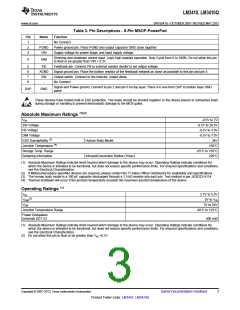
WSON and MSOP-PowerPad Packages
SOT-23 Package
Junction to Ambient
θJA
°C/W
(1)
0 LFPM Air Flow
118
18
WSON and MSOP-PowerPad Packages
SOT-23 Package
(1)
θJC
Junction to Case
°C/W
°C
60
(2)
TSD
Thermal Shutdown Temperature
165
(1) Applies for packages soldered directly onto a 3” x 3” PC board with 2oz. copper on 4 layers in still air.
(2) Thermal shutdown will occur if the junction temperature exceeds the maximum junction temperature of the device.
4
Submit Documentation Feedback
Copyright © 2007–2013, Texas Instruments Incorporated
Product Folder Links: LM3410 LM3410Q

 TI [ TEXAS INSTRUMENTS ]