LM27761
ZHCSEO7C –OCTOBER 2015–REVISED JANUARY 2017
www.ti.com.cn
8.2.2.6 External Capacitor Selection
The LM27761 requires 4 external capacitors for proper operation. Surface-mount multi-layer ceramic capacitors
are recommended. These capacitors are small, inexpensive, and have very low ESR (≤ 15 mΩ typical). Tantalum
capacitors, OS-CON capacitors, and aluminum electrolytic capacitors generally are not recommended for use
with the LM27761 due to their high ESR compared to ceramic capacitors.
For most applications, ceramic capacitors with an X7R or X5R temperature characteristic are preferable for use
with the LM27761. These capacitors have tight capacitance tolerances (as good as ±10%) and hold their value
over temperature (X7R: ±15% over –55°C to +125°C; X5R ±15% over –55°C to +85°C).
Using capacitors with a Y5V or Z5U temperature characteristic is generally not recommended for the LM27761.
These capacitors typically have wide capacitance tolerance (80%, ….20%) and vary significantly over
temperature (Y5V: 22%, –82% over –30°C to +85°C range; Z5U: 22%, –56% over 10°C to 85°C range). Under
some conditions a 1-µF-rated Y5V or Z5U capacitor could have a capacitance as low as 0.1 µF. Such
detrimental deviation is likely to cause Y5V and Z5U capacitors to fail to meet the minimum capacitance
requirements of the LM27761.
Net capacitance of a ceramic capacitor decreases with increased DC bias. This degradation can result in lower-
than-expected capacitance on the input and/or output, resulting in higher ripple voltages and currents. Using
capacitors at DC bias voltages significantly below the capacitor voltage rating usually minimizes DC bias effects.
Consult capacitor manufacturers for information on capacitor DC bias characteristics.
Capacitance characteristics can vary quite dramatically with different application conditions, capacitor types, and
capacitor manufacturers. TI strongly recommends that the LM27761 circuit be evaluated thoroughly early in the
design-in process with the mass-production capacitor of choice. This helps ensure that any such variability in
capacitance does not negatively impact circuit performance.
8.2.2.6.1 Charge-Pump Output Capacitor
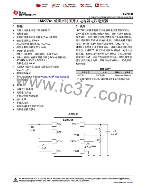
In typical applications, a 4.7-µF low-ESR ceramic charge-pump output capacitor (C3) is recommended. Different
output capacitance values can be used to reduce charge pump ripple, shrink the solution size, and/or cut the
cost of the solution. However, changing the output capacitor may also require changing the flying capacitor or
input capacitor to maintain good overall circuit performance.
In higher-current applications, a 10-µF, 10-V low-ESR ceramic output capacitor is recommended. If a small
output capacitor is used, the output ripple can become large during the transition between PFM mode and
constant switching. To prevent toggling, a 2-µF capacitance is recommended. For example, 10-µF, 10-V output
capacitor in a 0402 case size typically has only 2-µF capacitance when biased to 5 V.
8.2.2.6.2 Input Capacitor
The input capacitor (C2) is a reservoir of charge that aids in a quick transfer of charge from the supply to the
flying capacitors during the charge phase of operation. The input capacitor helps to keep the input voltage from
drooping at the start of the charge phase when the flying capacitors are connected to the input. It also filters
noise on the input pin, keeping this noise out of the sensitive internal analog circuitry that is biased off the input
line.
Input capacitance has a dominant and first-order effect on the input ripple magnitude. Increasing (decreasing) the
input capacitance results in a proportional decrease (increase) in input voltage ripple. Input voltage, output
current, and flying capacitance also affects input ripple levels to some degree.
In typical applications, a 4.7-µF low-ESR ceramic capacitor is recommended on the input. When operating near
the maximum load of 250 mA, after taking into the DC bias derating, a minimum recommended input capacitance
is 2 µF or larger. Different input capacitance values can be used to reduce ripple, shrink the solution size, and/or
cut the cost of the solution.
8.2.2.6.3 Flying Capacitor
The flying capacitor (C1) transfers charge from the input to the output. Flying capacitance can impact both output
current capability and ripple magnitudes. If flying capacitance is too small, the LM27761 may not be able to
regulate the output voltage when load currents are high. On the other hand, if the flying capacitance is too large,
the flying capacitor might overwhelm the input and charge pump output capacitors, resulting in increased input
and output ripple.
14
版权 © 2015–2017, Texas Instruments Incorporated

 TI [ TEXAS INSTRUMENTS ]