LM26420, LM26420-Q0, LM26420-Q1
www.ti.com
SNVS579J –FEBRUARY 2009–REVISED SEPTEMBER 2015
Thermal Considerations (continued)
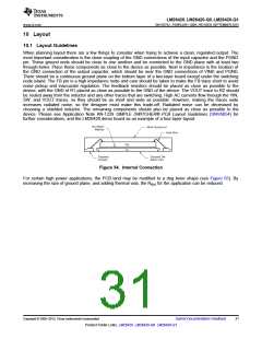
The PCB size, weight of copper used to route traces and ground plane, and number of layers within the PCB can
greatly affect RθJA. The type and number of thermal vias can also make a large difference in the thermal
impedance. Thermal vias are necessary in most applications. They conduct heat from the surface of the PCB to
the ground plane. Five to eight thermal vias should be placed under the exposed pad to the ground plane if the
WQFN package is used. Up to 12 thermal vias should be used in the HTSSOP-20 package for optimum heat
transfer from the device to the ground plane.
Thermal impedance also depends on the thermal properties of the application's operating conditions (VIN, VOUT
,
IOUT, etc.), and the surrounding circuitry.
10.3.1 Method 1: Silicon Junction Temperature Determination
To accurately measure the silicon temperature for a given application, two methods can be used. The first
method requires the user to know the thermal impedance of the silicon junction to top case temperature.
Some clarification needs to be made before we go any further.
R
θJC is the thermal impedance from silicon junction to the exposed pad.
θJT is the thermal impedance from top case to the silicon junction.
R
In this data sheet we will use RθJT so that it allows the user to measure top case temperature with a small
thermocouple attached to the top case.
RθJT is approximately 20°C/W for the 16-pin WQFN package with the exposed pad. Knowing the internal
dissipation from the efficiency calculation given previously, and the case temperature, which can be empirically
measured on the bench we have:
TJ - TT
RTJTꢀ
=
PINTERNAL
(37)
(38)
(39)
Therefore:
TJ = (RθJT × PINTERNAL) + TC
From the previous example:
TJ = 20°C/W × 0.304W + TC
10.3.2 Thermal Shutdown Temperature Determination
The second method, although more complicated, can give a very accurate silicon junction temperature.
The first step is to determine RθJA of the application. The LM26420 has over-temperature protection circuitry.
When the silicon temperature reaches 165°C, the device stops switching. The protection circuitry has a
hysteresis of about 15°C. Once the silicon junction temperature has decreased to approximately 150°C, the
device will start to switch again. Knowing this, the RθJA for any application can be characterized during the early
stages of the design one may calculate the RθJA by placing the PCB circuit into a thermal chamber. Raise the
ambient temperature in the given working application until the circuit enters thermal shutdown. If the SW pin is
monitored, it will be obvious when the internal FETs stop switching, indicating a junction temperature of 165°C.
Knowing the internal power dissipation from the above methods, the junction temperature, and the ambient
temperature RθJA can be determined.
165°- T A
RTJAꢀ=
PINTERNAL
(40)
Once this is determined, the maximum ambient temperature allowed for a desired junction temperature can be
found.
An example of calculating RθJA for an application using the LM26420 WQFN demonstration board is shown
below.
The four layer PCB is constructed using FR4 with 1 oz copper traces. The copper ground plane is on the bottom
layer. The ground plane is accessed by eight vias. The board measures 3 cm × 3 cm. It was placed in an oven
with no forced airflow. The ambient temperature was raised to 152°C, and at that temperature, the device went
into thermal shutdown.
Copyright © 2009–2015, Texas Instruments Incorporated
Submit Documentation Feedback
33
Product Folder Links: LM26420 LM26420-Q0 LM26420-Q1

 TI [ TEXAS INSTRUMENTS ]