LM26420, LM26420-Q0, LM26420-Q1
SNVS579J –FEBRUARY 2009–REVISED SEPTEMBER 2015
www.ti.com
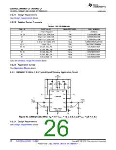
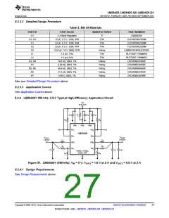
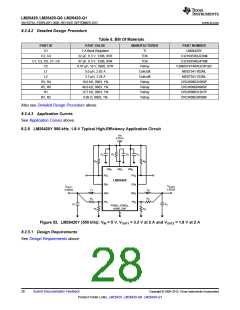
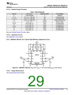
8.2.6.2 Detailed Design Procedure
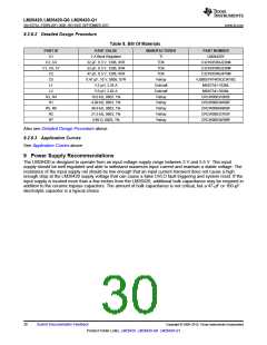
Table 8. Bill Of Materials
PART ID
U1
PART VALUE
MANUFACTURER
PART NUMBER
2 A Buck Regulator
22 µF, 6.3 V, 1206, X5R
33 µF, 6.3 V, 1206, X5R
47 µF, 6.3 V, 1206, X5R
0.47 µF, 10 V, 0805, X7R
3.3 µH, 3.28 A
TI
LM26420Y
C3216X5R0J226M
C3216X5R0J336M
C3216X5R0J476M
VJ0805Y474KXQCW1BC
MSS7341-332NL
C3, C4
C1, C6, C7
C2
TDK
TDK
TDK
C5
Vishay
Coilcraft
Coilcraft
Vishay
Vishay
Vishay
Vishay
Vishay
L1
L2
5.0 µH, 2.82 A
MSS7341-502NL
R3, R4
R1
10.0 kΩ, 0603, 1%
4.99 kΩ, 0603, 1%
49.9 kΩ, 0603, 1%
21.5 kΩ, 0603, 1%
4.99 Ω, 0603, 1%
CRCW060310K0F
CRCW06034K99F
CRCW060649K9F
CRCW060321K5F
CRCW06034R99F
R5, R6
R2
R7
Also see Detailed Design Procedure above.
8.2.6.3 Application Curves
See Application Curves above.
9 Power Supply Recommendations
The LM26420 is designed to operate from an input voltage supply range between 3 V and 5.5 V. This input
supply should be well regulated and able to withstand maximum input current and maintain a stable voltage. The
resistance of the input supply rail should be low enough that an input current transient does not cause a high
enough drop at the LM26420 supply voltage that can cause a false UVLO fault triggering and system reset. If the
input supply is located more than a few inches from the LM26420, additional bulk capacitance may be required in
addition to the ceramic bypass capacitors. The amount of bulk capacitance is not critical, but a 47-μF or 100-μF
electrolytic capacitor is a typical choice.
30
Submit Documentation Feedback
Copyright © 2009–2015, Texas Instruments Incorporated
Product Folder Links: LM26420 LM26420-Q0 LM26420-Q1

 TI [ TEXAS INSTRUMENTS ]