INA282, INA283
INA284, INA285
INA286
SBOS485A –NOVEMBER 2009–REVISED JULY 2010
www.ti.com
EXTENDED NEGATIVE COMMON-MODE RANGE
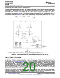
Using a negative power supply can extend the common-mode range 14V more negative than the supply used.
For instance, a –10V supply allows up to –24V negative common-mode. Remember to keep the total voltage
between the GND pin and V+ pin to less than 18V. The positive common-mode decreases by the same amount.
The reference input simplifies this type of operation because the output quiescent bias point is always based on
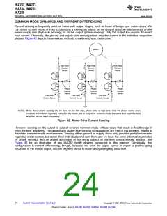
the reference connections. Figure 39 shows a circuit configuration for common-mode ranges from –24V to +70V.
Supply
-24V to +70V
Load
V+ = 5V
+IN
-IN
V+
1
Æ2
Æ2
Æ1
Æ2
Æ2
Æ1
Æ1
OUT
ZerÆ-
Drift
PRODUCT
GAIN
INA282
INA283
INA284
INA285
INA286
50V/V
200V/V
500V/V
1000V/V
100V/V
33.3kW
33.3kW
REF2
REF1
See Note (1)
GND
Connect to -10V
(1) Connect the REF pins as desired; however, they cannot exceed 9V above the GND pin voltage.
Figure 39. Circuit Configuration for Common-Mode Ranges from –24V to +70V
CALCULATING TOTAL ERROR
The electrical specifications for the INA282-286 family of devices include the typical individual errors terms such
as gain error, offset error, and nonlinearity error. Total error including all of these individual error components is
not specified in the Electrical Characteristics table. In order to accurately calculate the error that can be expected
from the device, we must first know the operating conditions to which the device is subjected. Some current
shunt monitors specify a total error in the product data sheet. However, this total error term is accurate under
only one particular set of operating conditions. Specifying the total error at this one point has little practical value
because any deviation from these specific operating conditions no longer yields the same total error value. This
section discusses the individual error sources, with information on how to apply them in order to calculate the
total error value for the device under any normal operating conditions.
The typical error sources that have the largest impact on the total error of the device are input offset voltage,
common-mode voltage rejection, gain error and nonlinearity error. For the INA282-286, an additional error source
referred to as Reference Common-Mode Rejection is also included in the total error value.
20
Submit Documentation Feedback
Copyright © 2009–2010, Texas Instruments Incorporated
Product Folder Link(s): INA282 INA283 INA284 INA285 INA286

 TI [ TEXAS INSTRUMENTS ]