INA282, INA283
INA284, INA285
INA286
SBOS485A –NOVEMBER 2009–REVISED JULY 2010
www.ti.com
APPLICATIONS INFORMATION
GENERAL INFORMATION
The INA282 family voltage output current shunt monitors feature a common-mode range that extends 14V below
the negative supply rail, as well as up to 80V, which allows use for either low-side or high-side current sensing.
BASIC CONNECTIONS
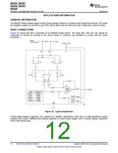
Figure 32 shows the basic connection of an INA282 family device. The input pins, +IN and –IN, should be
connected as closely as possible to the shunt resistor to minimize any resistance in series with the shunt
resistance.
Supply
-14V to +80V
+2.7V to +18V
Load
+IN
-IN
V+
1
Æ2
Æ2
Æ1
Æ2
Æ2
1
Æ1
OUT
ZerÆ-
Drift
Output
GAIN
PRODUCT
50V/V
INA282
INA286
INA283
INA284
INA285
100V/V
200V/V
500V/V
1000V/V
33.3kW
33.3kW
REF2
REF1
GND
Figure 32. Typical Application
Power-supply bypass capacitors are required for stability. Applications with noisy or high-impedance power
supplies may require additional decoupling capacitors to reject power-supply noise. Connect bypass capacitors
close to the device pins.
12
Submit Documentation Feedback
Copyright © 2009–2010, Texas Instruments Incorporated
Product Folder Link(s): INA282 INA283 INA284 INA285 INA286

 TI [ TEXAS INSTRUMENTS ]