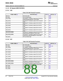
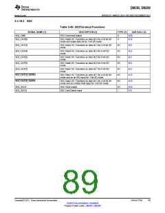
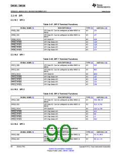
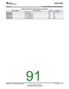
DM385, DM388
SPRS821D –MARCH 2013–REVISED DECEMBER 2013
www.ti.com
3.3.20 Supply Voltages
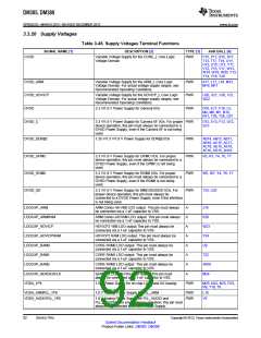
Table 3-45. Supply Voltages Terminal Functions
SIGNAL NAME [1]
DESCRIPTION [2]
TYPE [3]
AAR BALL [4]
CVDD
Variable Voltage Supply for the CORE_L Core Logic
Voltage Domain
PWR
P15, P17, R15, R17,
T13, T17, T18, U11,
U12, U15, U17, V11,
V12, V15, V17, W13,
W14, W19, W20, Y13,
Y14, Y19, Y20
CVDD_ARM
Variable Voltage Supply for the ARM_L Core Logic
Voltage Domain. For actual voltage supply ranges, see
Recommended Operating Conditions.
PWR
PWR
PWR
K17, L17, L18, M13,
M14, M17
CVDD_HDVICP
DVDD
Variable Voltage Supply for the HDVICP_L Core Logic
Voltage Domain. For actual voltage supply ranges, see
Recommended Operating Conditions.
U20, U21, V20, V21,
W22
3.3 V/1.8 V Power Supply for General I/Os
D16, E17, F16, L5,
M4, M6, M7, N10,
N11, T26, T28, U27
DVDD_C
3.3 V/1.8 V Power Supply for Camera I/F I/Os. For proper PWR
device operation, this pin must always be connected to a
DVDD Power Supply, even if the Camera I/F is not being
used.
D12, E13, F12, G12,
G13
DVDD_DDR[0]
DVDD_GPMC
DVDD_RGMII
DVDD_SD
1.35 V/1.5 V/1.8 V Power Supply for DDR[0] I/Os
PWR
PWR
PWR
PWR
AB14, AB15, AB17,
AB18, AC15, AC17,
AC18, AE15, AE16,
AF16, AG15, AH16
3.3 V/1.8 V Power Supply for GPMC I/Os. For proper
device operation, this pin must always be connected to a
DVDD Power Supply, even if the GPMC is not being
used.
R5, R7, T4, T6, T7
W5, W7, Y4, Y6, Y7
T25, U25
3.3 V/1.8 V Power Supply for RGMII I/Os. For proper
device operation, this pin must always be connected to a
DVDD Power Supply, even if the RGMII is not being
used.
3.3 V/1.8 V Power Supply for MMC/SD/SDIO I/Os. For
proper device operation, this pin must always be
connected to a DVDD Power Supply, even if the interface
is not being used.
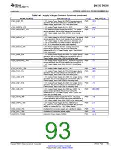
LDOCAP_ARM
ARM Cortex-A8 VBB LDO output. This pin must always
be connected via a 1-uF capacitor to VSS.
A
J19
LDOCAP_ARMRAM
LDOCAP_HDVICP
LDOCAP_HDVICPRAM
LDOCAP_RAM0
LDOCAP_RAM1
LDOCAP_RAM2
LDOCAP_SERDESCLK
VDDA_1P8
ARM Cortex-A8 RAM LDO output. This pin must always
be connected via a 1-uF capacitor to VSS.
A
K20
W23
Y24
U9
HDVICP2 VBB LDO output.This pin must always be
connected via a 1-uF capacitor to VSS.
A
HDVICP2 RAM LDO output. This pin must always be
connected via a 1-uF capacitor to VSS.
A
CORE RAM0 LDO output. This pin must always be
connected via a 1-uF capacitor to VSS.
A
CORE RAM1 LDO output. This pin must always be
connected via a 1-uF capacitor to VSS.
A
T22
AB10
M24
CORE RAM2 LDO output. This pin must always be
connected via a 1-uF capacitor to VSS.
A
SERDES_CLKP/N Pins LDO output. This pin must
always be connected via a 1-uF capacitor to VSS.
A
1.8 V Power Supply for on-chip LDOs and I/O biasing
PWR
M25, N22, N25, P23,
R9, T10, T9
VDDA_ARMPLL_1P8
VDDA_AUDIOPLL_1P8
1.8 V Analog Power Supply for PLL_ARM
PWR
PWR
L19
V9
1.8 V Analog Power Supply for PLL_AUDIO and
PLL_HDVPSS. For proper device operation, this pin must
always be connected to a 1.8-V Power Supply.
92
Device Pins
Copyright © 2013, Texas Instruments Incorporated
Submit Documentation Feedback
Product Folder Links: DM385 DM388

 TI [ TEXAS INSTRUMENTS ]