DM385, DM388
www.ti.com
SPRS821D –MARCH 2013–REVISED DECEMBER 2013
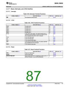
3.3.17 Reset, Interrupts, and JTAG Interface
3.3.17.1 Interupts
Table 3-35. Interrupts Terminal Functions
SIGNAL NAME [1]
DESCRIPTION [2]
Non-Maskable Interrupt input
TYPE [3]
AAR BALL [4]
AH31
NMI
I
3.3.17.2 JTAG
Table 3-36. JTAG Terminal Functions
SIGNAL NAME [1]
DESCRIPTION [2]
Emulator pin 0
TYPE [3]
I/O
AAR BALL [4]
A18
EMU0
EMU1
EMU2
EMU3
EMU4
RTCK
Emulator pin 1
I/O
B19
F24
C25
C28
N29
Emulator pin 2
I/O
Emulator pin 3
I/O
Emulator pin 4
I/O
JTAG return clock output. The internal pullup (IPU) is
enabled for this pin when the device is in reset and the
IPU is disabled (DIS) when reset is released.
O
TCLK
TDI
JTAG test clock input
JTAG test data input
I
T29
N28
U26
T31
I
TDO
TMS
JTAG test port data output
O
I
JTAG test port mode select input. For proper operation,
do not oppose the IPU on this pin.
TRST
JTAG test port reset input
I
U24
3.3.17.3 Reset
Table 3-37. Reset Terminal Functions
SIGNAL NAME [1]
DESCRIPTION [2]
Power-On Reset input
TYPE [3]
AAR BALL [4]
POR
I
AH30
AH29
AJ30
RESET
Device Reset input
I
RSTOUT_WD_OUT
Reset output (RSTOUT) or watchdog out (WD_OUT). If
this pin is unused, it can be left unconnected.
O
Copyright © 2013, Texas Instruments Incorporated
Device Pins
87
Submit Documentation Feedback
Product Folder Links: DM385 DM388

 TI [ TEXAS INSTRUMENTS ]