DM385, DM388
www.ti.com
SPRS821D –MARCH 2013–REVISED DECEMBER 2013
DEVICE
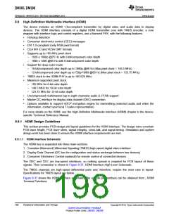
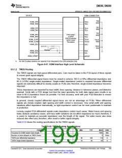
HDMI CONNECTOR
TD0
HDMI_DP0
TD0+
Shld
TD0-
HDMI_DN0
TD1
HDMI_DP1
HDMI_DN1
TD1+
Shld
TD1-
TD2
Shld
HDMI_DP2
HDMI_DN2
TPD12S521
or other
TD2+
TD2-
ESD Protection
w/I2C-Level
Translation
HDMI_CLKP
HDMI_CLKN
TCLK
TCLK
Shld
TCLK+
HDMI_CEC
CEC
DDC
Gnd
3.3 V
Rpullup(A)
HDMI_SDA
HDMI_SCL
SDA
SCL
HDMI_HPDET
HPDET
A. 5K-10K Ω pullup resistors are required if not integrated in the ESD protection chip.
Figure 8-37. HDMI Interface High-Level Schematic
8.9.1.2 TMDS Routing
The TMDS signals are high-speed differential pairs. Care must be taken in the PCB layout of these signals
to ensure good signal integrity.
The TMDS differential signal traces must be routed to achieve 100 Ω (±10%) differential impedance and
60 Ω (±10%) single-ended impedance. Single-ended impedance control is required because differential
signals are extremely difficult to closely couple on PCBs and, therefore, single-ended impedance becomes
important.
These impedances are impacted by trace width, trace spacing, distance to reference planes, and dielectric
material. Verify with a PCB design tool that the trace geometry for both data signal pairs results in as
close to 60 Ω impedance traces as possible. For best accuracy, work with your PCB fabricator to ensure
this impedance is met.
In general, closely coupled differential signal traces are not an advantage on PCBs. When differential
signals are closely coupled, tight spacing and width control is necessary. Very small width and spacing
variations affect impedance dramatically, so tight impedance control can be more problematic to maintain
in production.
Loosely coupled PCB differential signals make impedance control much easier. Wider traces and spacing
make obstacle avoidance easier, and trace width variations do not affect impedance as much; therefore, it
is easier to maintain an accurate impedance over the length of the signal. The wider traces also show
reduced skin effect and, therefore, often result in better signal integrity.
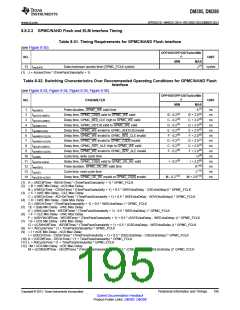
Table 8-33 shows the routing specifications for the TMDS signals.
Table 8-33. TMDS Routing Specifications
PARAMETER
Processor-to-HDMI header trace length
MIN
TYP
MAX
7000
0
UNIT
Mils
Stubs
Ω
Number of stubs allowed on TMDS traces
TX/RX pair differential impedance
TX/RX single ended impedance
90
54
100
60
110
66
Ω
Copyright © 2013, Texas Instruments Incorporated
Peripheral Information and Timings
199
Submit Documentation Feedback
Product Folder Links: DM385 DM388

 TI [ TEXAS INSTRUMENTS ]