DM385, DM388
SPRS821D –MARCH 2013–REVISED DECEMBER 2013
www.ti.com
8.9 High-Definition Multimedia Interface (HDMI)
The device includes an HDMI 1.3a-compliant transmitter for digital video and audio data to display
devices. The HDMI interface consists of a digital HDMI transmitter core with TMDS encoder, a core
wrapper with interface logic and control registers, and a transmit PHY, with the following features:
•
•
•
•
•
Hot-plug detection
Consumer electronics control (CEC) messages
DVI 1.0 compliant (only RGB pixel format)
CEA 861-D and VESA DMT formats
Supports up to 165-MHz pixel clock
–
–
1920 x 1080p @75 Hz with 8-bit/component color depth
1600 x 1200 @60 Hz with 8-bit/component color depth
•
Support for deep-color mode:
–
–
10-bit/component color depth up to 1080p @60 Hz (Max pixel clock = 148.5 MHz)
12-bit/component color depth up to 720p/1080i @60 Hz (Max pixel clock = 123.75 MHz)
•
•
TMDS clock to the HDMI-PHY is up to 185.625 MHz
Maximum supported pixel clock:
–
–
–
165 MHz for 8-bit color depth
148.5 MHz for 10-bit color depth
123.75 MHz for 12-bit color depth
•
•
•
Uncompressed multichannel (up to eight channels) audio (L-PCM) support
Master I2C interface for display data channel (DDC) connection
Options available to support HDCP encryption engine for transmitting protected audio and video (for
information, contact your local TI sales representative).
For more details on the HDMI, see the High-Definition Multimedia Interface (HDMI) chapter in the device-
specific Technical Reference Manual.
8.9.1 HDMI Design Guidelines
This section provides PCB design and layout guidelines for the HDMI interface. The design rules constrain
PCB trace length, PCB trace skew, signal integrity, cross-talk, and signal timing. Simulation and system
design work has been done to ensure the HDMI interface requirements are met.
8.9.1.1 HDMI Interface Schematic
The HDMI bus is separated into three main sections:
1. Transition Minimized Differential Signaling (TMDS) high-speed digital video interface
2. Display Data Channel (I2C bus for configuration and status exchange between two devices)
3. Consumer Electronics Control (optional) for remote control of connected devices.
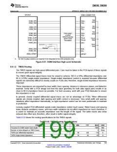
The DDC and CEC are low-speed interfaces, so nothing special is required for PCB layout of these
signals. Their connection is shown in Figure 8-37, HDMI Interface High-Level Schematic.
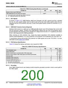
The TMDS channels are high-speed differential pairs and, therefore, require the most care in layout.
Specifications for TMDS layout are below.
Figure 8-37 shows the HDMI interface schematic. The specific pin numbers can be obtained from , HDMI
Terminal Functions.
198
Peripheral Information and Timings
Copyright © 2013, Texas Instruments Incorporated
Submit Documentation Feedback
Product Folder Links: DM385 DM388

 TI [ TEXAS INSTRUMENTS ]